Datasheet 搜索 > 微控制器 > TI(德州仪器) > TMS320F28335PTPQ 数据手册 > TMS320F28335PTPQ 产品设计参考手册 5/199 页

 器件3D模型
¥ 79.832
TMS320F28335PTPQ 产品设计参考手册 - TI(德州仪器)
制造商:
TI(德州仪器)
分类:
微控制器
封装:
LQFP-176
描述:
TEXAS INSTRUMENTS TMS320F28335PTPQ 芯片, 数字信号控制器, LQFP-176
Pictures:
3D模型
符号图
焊盘图
引脚图
产品图
页面导航:
引脚图在P14P79P80Hot
典型应用电路图在P48P95
原理图在P33P58P65P73P75P78P87P94P97P100P106
封装尺寸在P189P190P191
标记信息在P189P190P191P192
封装信息在P11P12P13P189P190P191P192
技术参数、封装参数在P45P46P116P117P118P119P120P121P122P123P124P125
应用领域在P61P113P140P199
电气规格在P46P116P117P118P119P120P121P122P123P124P125P126
导航目录
TMS320F28335PTPQ数据手册
Page:
of 199 Go
若手册格式错乱,请下载阅览PDF原文件

TMS320F28335, TMS320F28334, TMS320F28332
TMS320F28235, TMS320F28234, TMS320F28232
www.ti.com
SPRS439M –JUNE 2007–REVISED AUGUST 2012
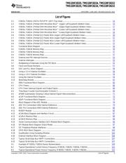
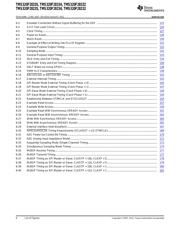
List of Figures
2-1 F2833x, F2823x 176-Pin PGF/PTP LQFP (Top View)...................................................................... 14
2-2 F2833x, F2823x 179-Ball ZHH MicroStar BGA™ (Upper Left Quadrant) (Bottom View) .............................. 16
2-3 F2833x, F2823x 179-Ball ZHH MicroStar BGA™ (Upper Right Quadrant) (Bottom View)............................. 17
2-4 F2833x, F2823x 179-Ball ZHH MicroStar BGA™ (Lower Left Quadrant) (Bottom View) .............................. 18
2-5 F2833x, F2823x 179-Ball ZHH MicroStar BGA ™(Lower Right Quadrant) (Bottom View)............................. 19
2-6 F2833x, F2823x 176-Ball ZJZ Plastic BGA (Upper Left Quadrant) (Bottom View)...................................... 20
2-7 F2833x, F2823x 176-Ball ZJZ Plastic BGA (Upper Right Quadrant) (Bottom View).................................... 21
2-8 F2833x, F2823x 176-Ball ZJZ Plastic BGA (Lower Left Quadrant) (Bottom View)...................................... 22
2-9 F2833x, F2823x 176-Ball ZJZ Plastic BGA (Lower Right Quadrant) (Bottom View).................................... 22
3-1 Functional Block Diagram ...................................................................................................... 34
3-2 F28335, F28235 Memory Map ................................................................................................. 36
3-3 F28334, F28234 Memory Map ................................................................................................. 37
3-4 F28332, F28232 Memory Map ................................................................................................. 37
3-5 External and PIE Interrupt Sources............................................................................................ 53
3-6 External Interrupts................................................................................................................ 53
3-7 Multiplexing of Interrupts Using the PIE Block ............................................................................... 54
3-8 Clock and Reset Domains ...................................................................................................... 57
3-9 OSC and PLL Block Diagram................................................................................................... 58
3-10 Using a 3.3-V External Oscillator............................................................................................... 59
3-11 Using a 1.9-V External Oscillator............................................................................................... 59
3-12 Using the Internal Oscillator .................................................................................................... 59
3-13 Watchdog Module................................................................................................................ 62
4-1 DMA Functional Block Diagram ................................................................................................ 65
4-2 CPU-Timers....................................................................................................................... 66
4-3 CPU-Timer Interrupt Signals and Output Signal ............................................................................. 66
4-4 Time-Base Counter Synchronization Scheme 3 ............................................................................. 68
4-5 ePWM Submodules Showing Critical Internal Signal Interconnections................................................... 71
4-6 eCAP Functional Block Diagram............................................................................................... 73
4-7 eQEP Functional Block Diagram............................................................................................... 75
4-8 Block Diagram of the ADC Module ............................................................................................ 78
4-9 ADC Pin Connections With Internal Reference .............................................................................. 79
4-10 ADC Pin Connections With External Reference ............................................................................. 80
4-11 McBSP Module .................................................................................................................. 84
4-12 eCAN Block Diagram and Interface Circuit ................................................................................... 87
4-13 eCAN-A Memory Map ........................................................................................................... 88
4-14 eCAN-B Memory Map ........................................................................................................... 89
4-15 Serial Communications Interface (SCI) Module Block Diagram............................................................ 94
4-16 SPI Module Block Diagram (Slave Mode) .................................................................................... 97
4-17 I2C Peripheral Module Interfaces .............................................................................................. 98
4-18 GPIO MUX Block Diagram .................................................................................................... 100
4-19 Qualification Using Sampling Window ....................................................................................... 105
4-20 External Interface Block Diagram............................................................................................. 106
4-21 Typical 16-bit Data Bus XINTF Connections................................................................................ 107
4-22 Typical 32-bit Data Bus XINTF Connections................................................................................ 107
5-1 Example of F2833x, F2823x Device Nomenclature........................................................................ 109
6-1 Typical Operational Current Versus Frequency (F28335, F28235, F28334, F28234)................................. 122
6-2 Typical Operational Power Versus Frequency (F28335, F28235, F28334, F28234).................................. 122
Copyright © 2007–2012, Texas Instruments Incorporated List of Figures 5
器件 Datasheet 文档搜索
AiEMA 数据库涵盖高达 72,405,303 个元件的数据手册,每天更新 5,000 多个 PDF 文件
