Datasheet 搜索 > EEPROM芯片 > Microchip(微芯) > 25LC256T-I/ST 数据手册 > 25LC256T-I/ST 开发手册 1/14 页
 器件3D模型
¥ 14.78
25LC256T-I/ST 开发手册 - Microchip(微芯)
制造商:
Microchip(微芯)
分类:
EEPROM芯片
封装:
TSSOP-8
描述:
25LC256系列 256Kb (32Kx8) 2.5V TSSOP-8 串行 SPI总线 电可擦除 工业温度 卷盘
Pictures:
3D模型
符号图
焊盘图
引脚图
产品图
页面导航:
功能描述在P2
导航目录
25LC256T-I/ST数据手册
Page:
of 14 Go
若手册格式错乱,请下载阅览PDF原文件
© 2008 Microchip Technology Inc. DS01197A-page 1
AN1197
INTRODUCTION
The 25XXX series serial EEPROMs from Microchip
Technology support a half-duplex protocol that
functions on a master-slave paradigm that is ideally
suited to data stream applications. The bus is
controlled by the microcontroller (master), which
accesses the 25XXX serial EEPROM (slave) via a
simple Serial Peripheral Interface (SPI) compatible
serial bus. Bus signals required are a clock input (SCK)
plus separate data in (SI) and data out (SO) lines.
Access to the 25XXX serial EEPROM is controlled
through a Chip Select (
CS) input. Maximum clock
frequencies range from 3 MHz to 20 MHz.
Communication to the 25XXX serial EEPROM can be
paused via the hold pin (
HOLD) if the clock line is
shared with other peripherals on the SPI bus. While the
EEPROM is paused, transitions on its inputs are
ignored, with the exception of
CS, allowing the MCU to
service higher priority interrupts. After releasing the
HOLD pin, operations resume from the point when the
hold was asserted.
The main features of the 25XXX serial EEPROMs are:
• SPI-compatible serial interface bus
• EEPROM densities from 128 bits to 512 Kbits
• Bus speed from 3 MHz to 20 MHz
• Voltage range from 1.8V to 5.5V
• Low power operation
• Temperature range from -40°C to +125°C
• Over 1,000,000 erase/write cycles
• Built-in write protection
This application note is part of a series that provide
source code to help users implement the protocol with
minimal effort.
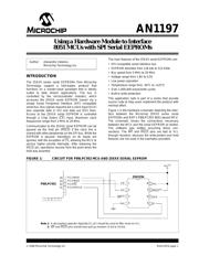
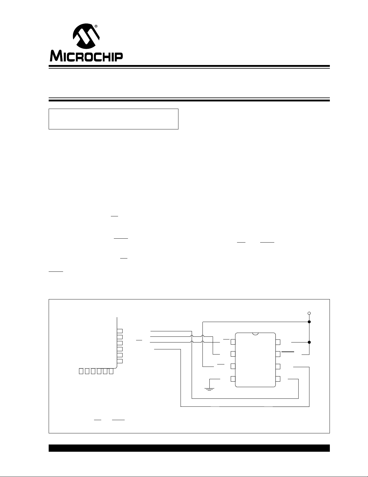
Figure 1 is the hardware schematic depicting the inter-
face between the Microchip 25XXX series serial
EEPROMs and NXP’s P89LPC952 8051-based MCU.
The schematic shows the connections necessary
between the MCU and the serial EEPROM as tested.
The software was written assuming these con-
nections. The
WP and HOLD pins are tied to VCC
through resistors, because the write-protect and hold
features are not used in the examples provided.
FIGURE 1: CIRCUIT FOR P89LPC952 MCU AND 25XXX SERIAL EEPROM
Author: Alexandru Valeanu
Microchip Technology Inc.
Note 1: A decoupling capacitor (typically 0.1 µF) should be used to filter noise on VCC.
CS
SO
WP
(2)
V
ss
V
cc
HOLD
(2)
SCK
SI
1
2
3
4
8
7
6
5
V
cc
(1)
P89LPC952
P2.5/SPICLK
P2.4/SS
P2.3/MISO
P2.1/MOSI
34
33
32
31
25XX256
Note 2: WP and HOLD pins should have pull-up resistors (2 kΩ to 10 kΩ).
Using a Hardware Module to Interface
8051 MCUs with SPI Serial EEPROMs
器件 Datasheet 文档搜索
AiEMA 数据库涵盖高达 72,405,303 个元件的数据手册,每天更新 5,000 多个 PDF 文件
