Datasheet 搜索 > 贴片电感 > Wurth Electronics(伍尔特) > 74477410 数据手册 > 74477410 开发手册 1/6 页

¥ 11.686
74477410 开发手册 - Wurth Electronics(伍尔特)
制造商:
Wurth Electronics(伍尔特)
分类:
贴片电感
封装:
5.8mm x 5.2mm x 4.5mm
描述:
WURTH ELEKTRONIK 74477410 表面贴装功率电感器, WE-PD2系列, 10 µH, ± 20%, 非屏蔽, 0.1 ohm, 2.2 A
Pictures:
3D模型
符号图
焊盘图
引脚图
产品图
页面导航:
应用领域在P6
导航目录
74477410数据手册
Page:
of 6 Go
若手册格式错乱,请下载阅览PDF原文件
ANP005b; 2012-06-14, StK Page 1 of 6
APPLICATI ON NO TE
EMC Filter for DC/DC switching controller optimized
ANP005B BY STEFAN KLEIN
1. Efficiency versus EMC________________________________________
Modern power supplies need to reduce power loss to maintain a high degree of efficiency. Switch mode
power supplies and DC/DC switching controllers are state of the art and allow great efficiency, but if the
design of the circuit and circuit board layout is less than ideal this can result in increased emission of radio
interference voltage. This article discusses the systematic implementation of input filters for reducing
symmetric interfering voltage in DC/DC switching controllers.
2. Demand for an input filter _____________________________________
Whether you have a switch mode power supply or DC/DC switching controller, every type of switch mode
power supply creates a broadband interference emission in the form of interfering voltage and interference
fields that can make other electrical devices malfunction. The main cause for the interfering voltage is current
at the input that flows through the input capacitor of the switching controller with the clock frequency of the
switching controller. It causes a voltage drop V
Rippel
via the ESR that consists of a proportional percentage by
the ESR and an integrated percentage by the capacity.
3. Measurement of the interfering voltage _________________________
This can be corrected by an input filter that reduces the amplitude of the interfering voltage, suppresses
harmonics and plays a vital role in reducing the radio interference voltage to an acceptable level. For
example, the generic standard EN61000-6-4 establishes at 150 kHz a limit value of the virtual peak value of
79 dBµV. The current market for passive components offers a broad portfolio of "ready-made filters" that are
marketed with high insertion loss. Insertion losses between 70 dB and 100 dB are declared, for example. But
these values are rarely achieved in practice because such filters were measured in a 50 Ω system and the
impedances of the power supplies deviate from these values. The development of an individual filter is
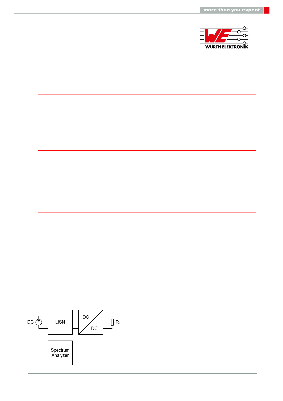
recommended. To begin with, the interference type should be identified for developing an input filter. A
distinction must be made between differential mode and common mode noise. A filter is employed at the
input of the switching controller to suppress the differential mode noise. Even during development, the
measurement of the interfering voltage can be carried out with an LISN (Line Impedance Stabilization
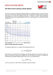
Network) and a spectrum analyzer. Fig. 1 shows the test setup of such a measurement process. Based on
such a setup, the pure differential mode noises can be measured because the reference potential is the
switching ground and not the reference ground.
Image 1: Test set up
器件 Datasheet 文档搜索
AiEMA 数据库涵盖高达 72,405,303 个元件的数据手册,每天更新 5,000 多个 PDF 文件
