Datasheet 搜索 > 微控制器 > Microchip(微芯) > DSPIC30F4012-30I/SP 数据手册 > DSPIC30F4012-30I/SP 开发手册 2/18 页
 器件3D模型
¥ 66.827
DSPIC30F4012-30I/SP 开发手册 - Microchip(微芯)
制造商:
Microchip(微芯)
分类:
微控制器
封装:
DIP-28
描述:
MICROCHIP DSPIC30F4012-30I/SP 芯片, 16位数字信号控制器, 48K闪存, 20MIPS
Pictures:
3D模型
符号图
焊盘图
引脚图
产品图
页面导航:
原理图在P2P5
导航目录
DSPIC30F4012-30I/SP数据手册
Page:
of 18 Go
若手册格式错乱,请下载阅览PDF原文件
SINUSOIDAL CONTROL OF PMSM MOTORS WITH DSPIC30F DSC
DS01017A-page 2 © 2005 Microchip Technology Inc.
It is strongly recommended that you read the
“PICDEM™ MCLV Development Board User’s Guide”
(DS51554) to fully understand the hardware topology
being used in this application note. This User’s Guide
can be downloaded from the Microchip web site.
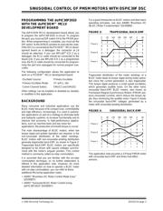
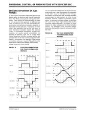
Figure 2 is a simplified system block diagram for a
Sinusoidal PMSM motor control application. This
diagram will help you develop your own hardware.
FIGURE 2: SYSTEM BLOCK DIAGRAM
Salient aspects of this topology are:
• Potentiometer R14 selects the desired speed
(Reference Speed)
• Rotor position is detected using Hall effect
sensors connected to pins RB3, RB4 and RB5
• Current feedback is provided through a simple
operational amplifier circuit
• Fault input is received through a comparator cir-
cuit connected with the current feedback circuit.
The current is sensed using a 0.1 ohm resistor
(R26)
You can easily adjust the values of the resistors to
accommodate the current capabilities of the motor
being used for your application. The motor drive circuit,
on the other hand, is designed to drive a 24V PMSM
motor. You can change the hardware to meet the drive
requirement of a specific motor.
On the low side, the voltage limit is 10V. On the high
side, the voltage limit is 48V. It is important to note that
the heat sink on the IGBTs have very limited heat dissi-
pation, so high power requirements may not be easily
met with the PICDEM™ MCLV development board.
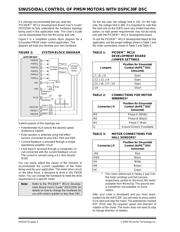
To use the PICDEM™ MCLV development board for this
application, use the jumper settings shown in Table 1 and
the motor connections shown in Table 2 and Table 3.
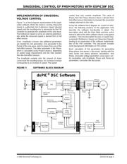
TABLE 1: PICDEM™ MCLV
DEVELOPMENT BOARD
JUMPER SETTINGS
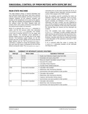
TABLE 2: CONNECTIONS FOR MOTOR
WINDINGS*
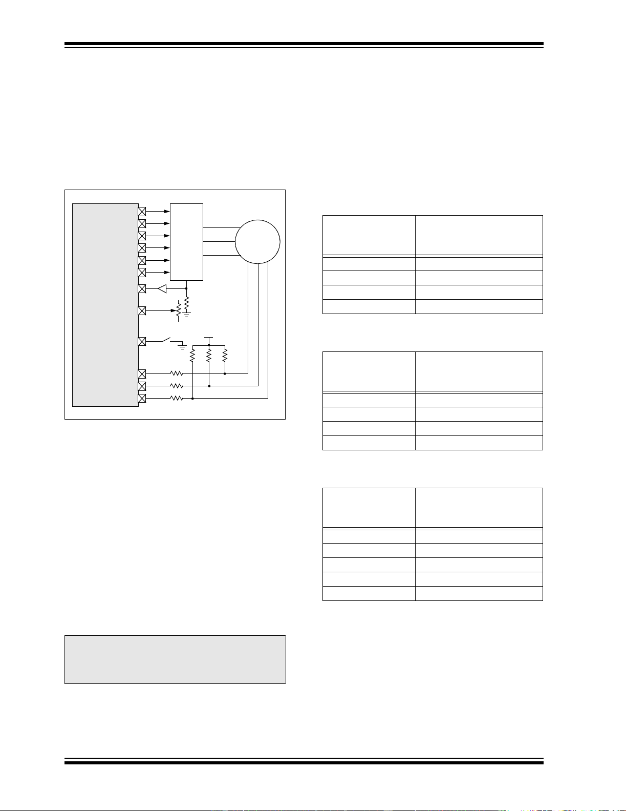
TABLE 3: MOTOR CONNECTIONS FOR
HALL SENSORS*
* The colors referenced in Tables 2 and 3 for
the motor windings and hall sensors,
respectively, pertain to the Hurst 24V motor
available from Microchip. The ground wire
is sometimes not available on some
motors.
After your code is developed and you have down-
loaded it to the dsPIC30F, you will need to press switch
S2 to start and stop the motor. The potentiomer marked
REF (R14) sets the required speed and direction of
rotation of the motor. The motor does not need to stop
to change direction of rotation.
Note: Refer to the “PICDEM™ MCLV Develop-
ment Board User’s Guide” (DS51554) for
details on how to change the hardware for
use with motors greater or less than 24V.
PWM3H
PWM3L
dsPIC30F2010
PWM2H
PWM2L
PWM1H
PWM1L
AN1
AN2
RC14
RB3/CN5
RB4/IC7
RB5/IC8
3-Phase
Inverter
3-Phase
PMSM
Motor
Phase A
Phase B
Phase C
Reference
Speed
S2
+5V
Start/Stop
R24 R23 R20
R21
R22
R25
Hall A
Hall B
Hall C
IBUS
R26
R14
Jumpers
Position for Sinusoidal
Control (dsPIC
®
DSC
Sensored)
J7, J8, J11 Open
J12, J13, J14 Open
J15, J16, J17, J10 Open
J19 Short
Connector J9
Position for Sinusoidal
Control (dsPIC
®
DSC
Sensored)
M3 Phase A (White)
M2 Phase B (Black)
M1 Phase C (Red)
G Ground (Green) if available
Connector J9
Position for Sinusoidal
Control (dsPIC
®
DSC
Sensored)
+5V Red
GND Black
HA White
HB Brown
HC Green
器件 Datasheet 文档搜索
AiEMA 数据库涵盖高达 72,405,303 个元件的数据手册,每天更新 5,000 多个 PDF 文件
