Datasheet 搜索 > AD转换器 > Microchip(微芯) > MCP3204-CI/ST 数据手册 > MCP3204-CI/ST 开发手册 1/10 页
 器件3D模型
¥ 26.775
MCP3204-CI/ST 开发手册 - Microchip(微芯)
制造商:
Microchip(微芯)
分类:
AD转换器
封装:
TSSOP-14
描述:
MCP30/MCP32/MCP33 系列逐次逼近寄存器 (SAR) 模拟至数字转换器### 模数转换器 - Microchip
Pictures:
3D模型
符号图
焊盘图
引脚图
产品图
页面导航:
原理图在P1
技术参数、封装参数在P7
应用领域在P7
导航目录
MCP3204-CI/ST数据手册
Page:
of 10 Go
若手册格式错乱,请下载阅览PDF原文件
2003 Microchip Technology Inc. DS00246A-page 1
M
AN246
INTRODUCTION
Driving any A/D Converter (ADC) can be challenging if
all issues and trade-offs are not well understood from
the beginning. With Successive Approximation Regis-
ter (SAR) ADCs, the sampling speed and source
impedance should be taken into consideration if the
device is to be fully utilized. In this application note we
will delve into the issues surrounding the SAR Con-
verter’s input and conversion nuances to insure that the
converter is handled properly from the beginning of the
design phase. We will also review the specifications
available in most A/D Converter data sheets and iden-
tify the important specifications for driving your SAR.
From this discussion, techniques will be explored which
can be used to successfully drive the input of the SAR
A/D Converter. Since most SAR applications require an
active driving device at the converter’s input, the final
subject will be to explore the impact of an operational
amplifier on the analog-to-digital conversion in terms of
DC as well as ac responses.
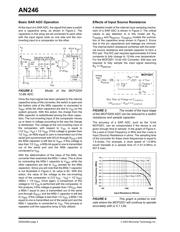
A typical system block diagram of the SAR converter
application is shown in Figure 1. Some common SAR
converter systems are Data Acquisition Systems,
Transducers Sensing Circuits, Battery Monitoring
applications and Data Logging. In all of these systems,
DC specifications are important. Additionally, the
required conversion rate is relatively fast (as compared
to Delta-Sigma converters) and having a lower number
of bits that are reliably converted is acceptable.
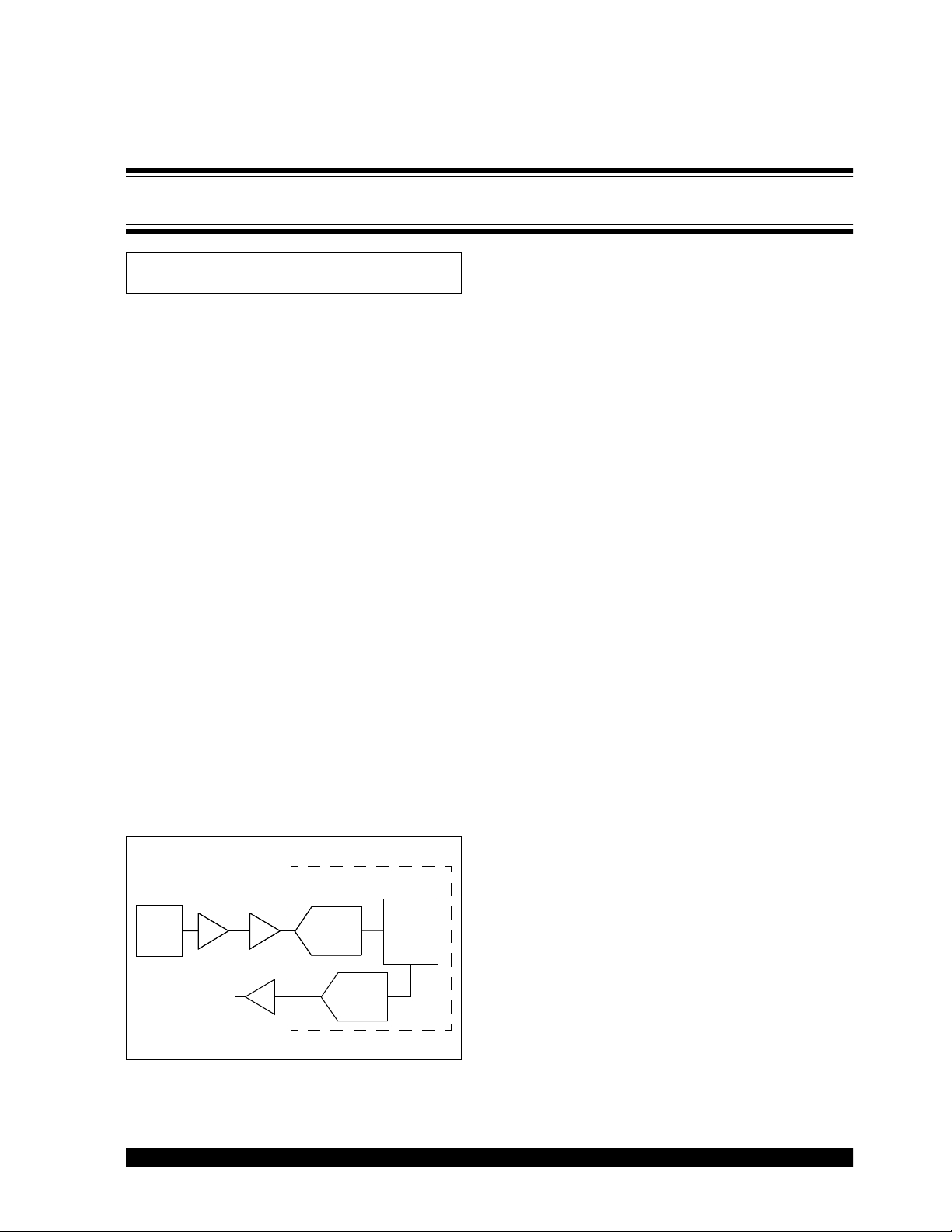
FIGURE 1: Block diagram of an
application that has a SAR ADC in the signal
path.
For the converter shown in Figure 1, the input signal
could be ac, DC or both. The operational amplifier is
used for gain, impedance isolation and its drive capa-
bility. A filter of some sort (passive or active) is needed
to reduce noise and to prevent aliasing errors.
The ADC in Figure 1 could be external or, in the case
of a SAR converter, internal to the microcontroller. The
DAC / PWM block can be implemented internally or
externally to the microcontroller as well. This function is
used to drive actuators, values, etc. A filter following
the DAC / PWM function is usually required to perform
a smoothing function. This filter would reduce glitch
errors, quantization errors and provide drive or isolation
to the actuator. In this discussion we will focus on the
input section to the A/D Converter.
BASIC OPERATION OF THE SAR ADC
With the SAR ADC, the input signal should be consid-
ered in the DC as well as ac domain. This is true even
if you are only interested in a DC response.
DC Errors of the SAR ADC
The offset and gain errors of an ADC can be easily cal-
ibrated out of the resulting data using the microcontrol-
ler at the output of the converter. But the more difficult
DC errors to calibrate out would be Integral Non-Lin-
earity (INL) and Differential Non-Linearity (DNL). In
most systems, these errors manifest themselves as
incorrect conversions or noise. Of the two specifica-
tions, INL is the “Holy Grail” of DC specifications
because it describes the entire transfer function. INL is
a measure of how close to actual the transition points
are to the ideal transfer function. This is a difficult error
to calibrate out with a microcontroller because every
code needs to be evaluated for proper calibration and
this error differs from device to device.
While noise is usually not a topic for DC accuracy, in
this case it has merit. It is important to realize that the
SAR ADC operates in the frequency domain. This is
true even though you may think that you are measuring
near DC signals. If there is a noise source in the sys-
tem, the “DC” conversion from sample-to-sample may
not be the same. This phenomena is reduced by using
anti-aliasing filters. When digitizing AC signals, other
characteristics of the converter come into play. These
characteristics include distortion of the input signal and
noise levels. Anti-aliasing filters are also useful for
these type of problems.
Author: Bonnie C. Baker
Microchip Technology Inc.
Filter
Amp
Filter
Micro-
controller
Engine
Output
Input
Signal
Source
Analog to
Digital
Converter
DAC or
PWM
Driving the Analog Inputs of a SAR A/D Converter
器件 Datasheet 文档搜索
AiEMA 数据库涵盖高达 72,405,303 个元件的数据手册,每天更新 5,000 多个 PDF 文件
