Datasheet 搜索 > AD转换器 > Microchip(微芯) > MCP3304-CI/P 数据手册 > MCP3304-CI/P 开发手册 1/7 页
 器件3D模型
¥ 43.442
MCP3304-CI/P 开发手册 - Microchip(微芯)
制造商:
Microchip(微芯)
分类:
AD转换器
封装:
DIP-16
描述:
MICROCHIP MCP3304-CI/P 模数转换器, AEC-Q100, 13 bit, 100 kSPS, 单, 4.5 V, 5.5 V, DIP
Pictures:
3D模型
符号图
焊盘图
引脚图
产品图
页面导航:
应用领域在P5


导航目录
MCP3304-CI/P数据手册
Page:
of 7 Go
若手册格式错乱,请下载阅览PDF原文件
1999 Microchip Technology Inc. DS00688B-page 1
AN688
Layout Tips for 12-Bit A/D Converter Application
INTRODUCTION
This Application Note originally started as a “cook
book” for a true 12-bit layout. The assumption of this
type of approach is that a reference design could be
provided, which easily could be used for every layout
implementation. But, the notion of this approach is fairly
unrealistic. There are a multitude of successful ways to
layout out systems with 12-bit Analog-to-Digital (A/D)
Converters and each layout is highly dependent on the
number of devices in the circuit, the types of the
devices (digital or analog) and the environment that the
final product will reside in. Given all of these variables,
it could easily be demonstrated that one successful lay-
out that provides twelve noise free bits from an analog
signal may easily fail in another setting.
Because of the complexity of this problem, this Applica-
tion Note will provide basic guidelines, ending with a
review of issues to be aware of. Throughout the appli-
cation note, examples of good layout and bad layout
implementations will be presented. This will be done in
the spirit of discussing concepts and not with the intent
of recommending one layout as the only one to use.
GETTING A GOOD START
Imagine that the task at hand is to design a pressure
sensing circuit that will accurately measure the pres-
sure and present the results on an LCD display screen.
Seems easy enough.
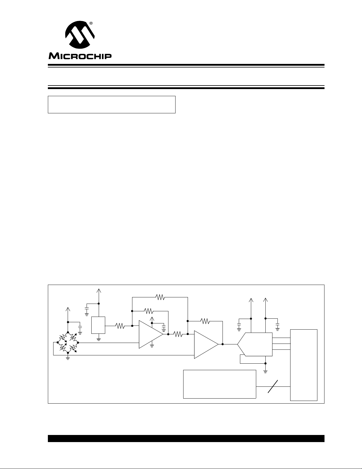
The circuit diagram for this system is shown in Figure 1.
The pressure sensor that is chosen for the job is a
piezo resistive sensor that is configured as a four ele-
ment bridge. The particular sensor that is selected
requires voltage excitation. The full swing output of the
sensor is a small (10s of millivolts) differential signal
that most appropriately is gained by an operational
amplifier structure that also converts the differential
output of the sensor to a single ended analog signal. A
12-bit converter is chosen to match the precision of the
pressure sensor. Once the converter digitizes the volt-
age presented at its input, the digital code is sent to a
microcontroller. The job of the microcontroller is to per-
form tasks such as calibration corrections and linear-
ization. Once this is done, the results are sent to the
LCD display.
The final step in the circuit development is to work
through the calibration and linearization issues associ-
ated with the pressure sensor. Once these issues are
settled, the microcontroller firmware is developed. Now
the board is ready to go to layout.
FIGURE 1: This is a pressure sensor application where the differential signal from the sensor is gained by an
instrumentation amplifier and digitized with a 12-bit A/D Converter, MCP3201. The results of the conversion is displayed
on the LCD display.
Author: Bonnie C. Baker
Microchip Technology Inc.
AD
680
1
/
2
MCP602
V
DD
8
7
6
5
1
2
4
R
1
R
G
R
2
LCD Display
PICmicro
®
R
2
R
1
1
/
2
MCP602
MCP3201
3
–
+
–
+
2.5V
12-Bit ADC
IA
OUT
IA–
IA+
IA
OUT
IA+ IA––()1
R
1
R
2
------
2R
1
R
G
---------++
2.5V+=
Pressure Sensor
器件 Datasheet 文档搜索
AiEMA 数据库涵盖高达 72,405,303 个元件的数据手册,每天更新 5,000 多个 PDF 文件
