Datasheet 搜索 > 微控制器 > Microchip(微芯) > PIC16C72A-20I/SP 数据手册 > PIC16C72A-20I/SP 开发手册 2/24 页
 器件3D模型
¥ 46.962
PIC16C72A-20I/SP 开发手册 - Microchip(微芯)
制造商:
Microchip(微芯)
分类:
微控制器
封装:
SPDIP-28
描述:
MICROCHIP PIC16C72A-20I/SP 微控制器, 8位, 一次性可编程, PIC16C7xx, 20 MHz, 3.5 KB, 128 Byte, 28 引脚, NDIP
Pictures:
3D模型
符号图
焊盘图
引脚图
产品图
页面导航:
原理图在P6P8
应用领域在P11P13
导航目录
PIC16C72A-20I/SP数据手册
Page:
of 24 Go
若手册格式错乱,请下载阅览PDF原文件
AN1310
DS01310A-page 2 2010 Microchip Technology Inc.
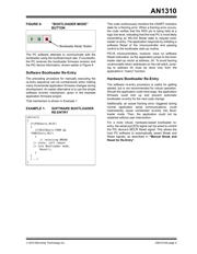
IMPLEMENTATION BASICS
This section gives the three basic steps for setting up
and using the bootloader for those already familiar with
bootloader/application development.
Subsequent sections provide overview and more
detailed information relating to these steps. Those
sections include:
• “Firmware Overview”
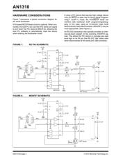
• “Hardware Considerations”
• “Bootloader Mode Considerations”
• “Application Mode Considerations”
• “Software Design”
Step 1:
Compile and Program Bootloader
Firmware
More detailed information on this step is provided in:
• “Firmware Overview”
• “Hardware Considerations”
• “Bootloader Mode Considerations”
• “Software Design”
By default, the serial bootloader installation provides
bootloader firmware source code in the PC path:
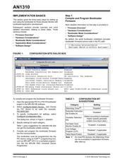
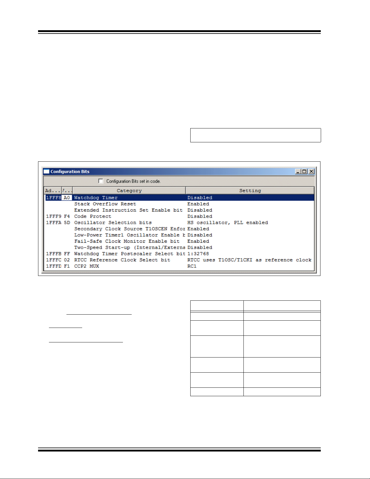
FIGURE 1: CONFIGURATION BITS DIALOG BOX
To compile and program the bootloader firmware:
1. Open the appropriate PIC16 or PIC18 bootloader
project in the MPLAB IDE software.
2. Select Configure>Select Device...
and choose
the PIC device to be used (for example,
PIC18F87J90
).
3. To specify Configuration bit settings, select
Configure>Configuration Bits...
.
The dialog box, shown in Figure 1, appears.
4. Specify settings for each category.
Table 1 gives suggestions for selected bits that
can get the bootloader initially working.
5. Compile and program the bootloader firmware
into the microcontroller.
The bootloader must be programmed into the
PIC device using an ICSP™ programming tool,
such as MPLAB
®
ICD 3 or a socketed program-
mer like the MPLAB PM3 Universal Device
Programmer.
C:\Microchip Solutions\Serial
Bootloader AN1310 vX.XX\PICxx Bootloader\
TABLE 1: CONFIGURATION BIT
SUGGESTIONS
Category Setting
Watchdog Timer
(1)
“Disabled”
Extended Instruction
Set Enable bit
“Disabled”
Oscillator Selection
bits
(Select according to hardware.
Higher speeds generally
enable more baud rates.)
Fail-Safe Clock
Monitor Enable bit
“Enabled”, if available
Low-Voltage
Program (LVP)
“Disabled”, if applicable
Table Read-Protect “Disabled”, if applicable
Note 1: On most PIC devices, the Watchdog Timer
can be re-enabled in application firmware
after start-up.
器件 Datasheet 文档搜索
AiEMA 数据库涵盖高达 72,405,303 个元件的数据手册,每天更新 5,000 多个 PDF 文件
