Datasheet 搜索 > 微控制器 > Microchip(微芯) > PIC16F1825T-I/ST 数据手册 > PIC16F1825T-I/ST 开发手册 6/24 页
 器件3D模型
¥ 6.4
PIC16F1825T-I/ST 开发手册 - Microchip(微芯)
制造商:
Microchip(微芯)
分类:
微控制器
封装:
TSSOP-14
描述:
PIC16 系列 1 KB RAM 14 kB 闪存 8 位 表面贴装 微控制器 - TSSOP-14
Pictures:
3D模型
符号图
焊盘图
引脚图
产品图
页面导航:
原理图在P6P8
应用领域在P11P13
导航目录
PIC16F1825T-I/ST数据手册
Page:
of 24 Go
若手册格式错乱,请下载阅览PDF原文件
AN1310
DS01310A-page 6 2010 Microchip Technology Inc.
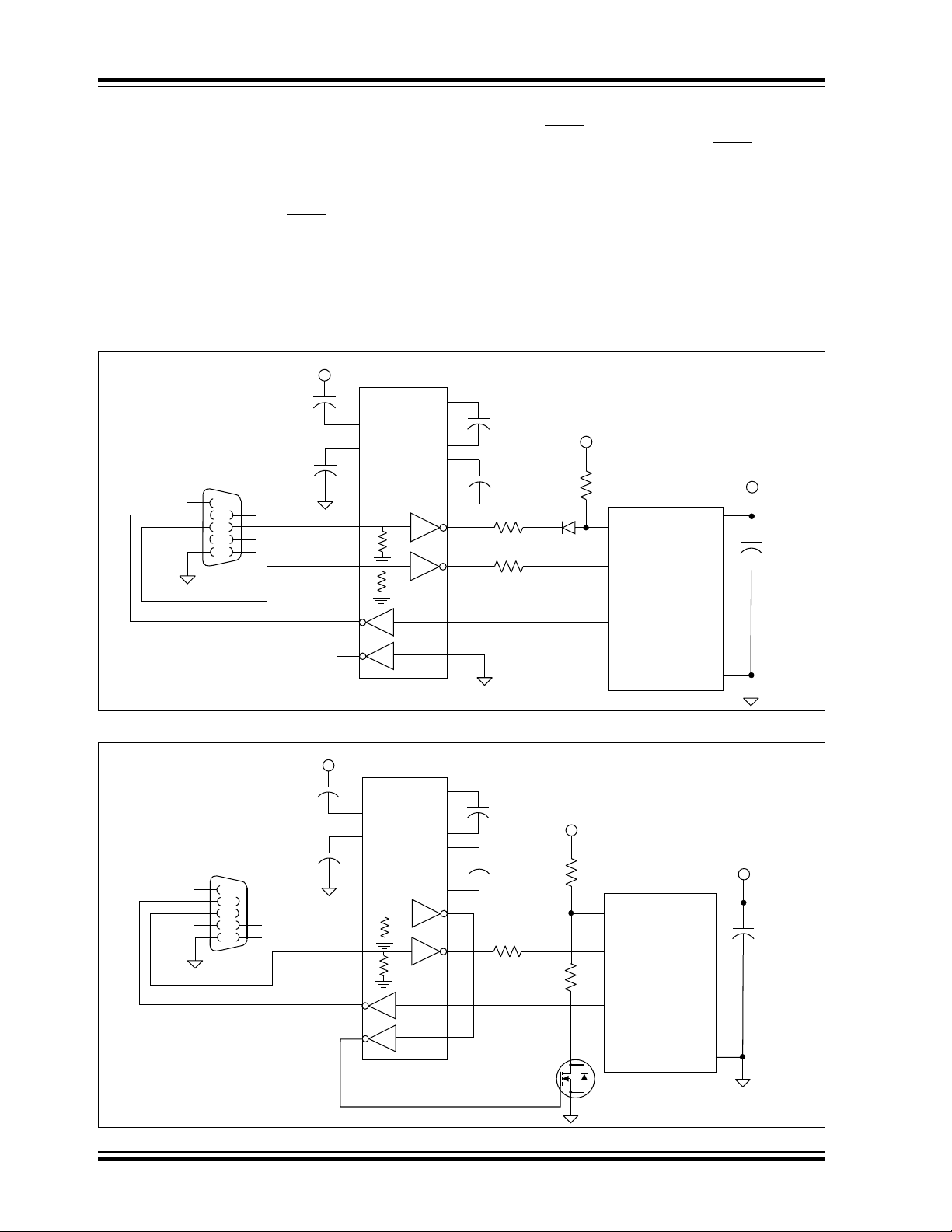
HARDWARE CONSIDERATIONS
Figure 7 represents a typical connection diagram for
the serial bootloader.
RTS-based MCLR Reset control is optional. When con-
nected, the host PC can use the RTS serial port signal
to pull down the PIC device’s MCLR
pin, allowing the
host PC software to automatically reset the device
when entering the Bootloader mode.
If using a PIC device that requires high voltage (above
V
DD) on MCLR to enter the In-Circuit Serial Program-
ming™ (ICSP™) mode, the RTS/MCLR
diode can
interfere with traditional ICSP programming/debug-
ging. In this case, using an N-channel metal oxide
semiconductor field effect transistor (MOSFET) may be
more appropriate. (See Figure 8.)
An RS-232 transceiver chip typically provides an inter-
nal pull-down resistor on the incoming TXD/RTS sig-
nals. This allows the PIC device to normally see logic
level high on its RX pin (the RS-232 “Idle” state) even
when disconnected at the serial port, DB9 connector.
FIGURE 7: RX PIN SCHEMATIC
FIGURE 8: MOSFET SCHEMATIC
C1
C2
R1
R2
D1
C1+
C1-
C2+
C2-
11
10
V+
2
V-
6
13
8
U2
R3
MCLR#
1
RC6/TX
25
RC7/RX
26
V
DD
U1
C5
RTS
0.1F
0.1F
0.1F
0.1F
10 k
+3.3V
GND
+3.3V
MAX3232
470
GND
+3.3V
1
4
5
6
8
9
3
2
7
+
+
+
470
V
SS
0.1F
J1
DB9
GND
RXD
TXD
C3
C4
1
3
4
5
11
12
PIC
®
Device
C1
C2
R1
R2
C1+
C1-
C2+
C2-
11
10
V+
2
V-
6
13
8
U2
MC LR #
1
RC6/TX
25
RC7/RX
26
V
DD
U1
C5
RTS
0.1F
0.1F
0.1F
0.1F
10 k
+5V
GND
+3.3V
Q1
2N7002
+5V
1
4
5
6
8
9
3
2
7
+
+
+
470
V
SS
0.1F
J1
DB9
GND
RXD
TXD
C3
C4
1
3
4
5
11
12
PIC
®
Device
R2
470
器件 Datasheet 文档搜索
AiEMA 数据库涵盖高达 72,405,303 个元件的数据手册,每天更新 5,000 多个 PDF 文件
