Datasheet 搜索 > 微控制器 > Microchip(微芯) > PIC16F1933-I/SP 数据手册 > PIC16F1933-I/SP 开发手册 1/24 页
 器件3D模型
¥ 18.813
PIC16F1933-I/SP 开发手册 - Microchip(微芯)
制造商:
Microchip(微芯)
分类:
微控制器
封装:
DIP-28
描述:
MICROCHIP PIC16F1933-I/SP 微控制器, 8位, 闪存, AEC-Q100, PIC16F19xx, 32 MHz, 7 KB, 256 Byte, 28 引脚, DIP
Pictures:
3D模型
符号图
焊盘图
引脚图
产品图
页面导航:
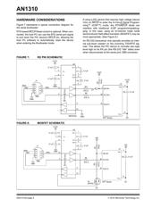
原理图在P6P8
应用领域在P11P13
导航目录
PIC16F1933-I/SP数据手册
Page:
of 24 Go
若手册格式错乱,请下载阅览PDF原文件

2010 Microchip Technology Inc. DS01310A-page 1
INTRODUCTION
Microchip’s enhanced Flash microcontrollers enable
firmware to program itself. This is done by a “boot-
loader” providing a firmware kernel, residing in the
microcontroller. The kernel uses a small portion of pro-
gram memory not normally used by the firmware’s
main application.
When the bootloader firmware is activated, a host PC
can use a serial protocol to read, write and verify
updates to the microcontroller's application firmware.
Once the application firmware is programmed, the
bootloader cedes control, allowing normal application
execution until the bootloader is called.
AN1310 Bootloader Features
The key features of the AN1310, “High-Speed Serial
Bootloader for PIC16 and PIC18 Devices” include:
• Small firmware code size (less than 450 instruction
words on most devices)
• Automatic baud rate synchronization to the host
• Baud rate flexibility, from 1,200 bps to 3 Mbps for
extremely fast programming
• A 16-bit CRC packet and Flash memory
verification for quick verification of successful
programming, even at low baud rates
• An advanced “write planner” that eliminates
unnecessary erase/write transactions
• Support for a wide variety of PIC16 and PIC18
devices through an “essential device characteristics”
database
• Optional application remapping that does not
require linker script modifications or remapping of
interrupt service routines
• A forced bootloader re-entry mechanism requiring
minimal start-up delay and no additional I/O pins or
application firmware code to re-enter the bootloader
• Optional MCLR
Reset control, allowing the host
PC application to automatically reset the device
for robust bootloader re-entry
• PC software rewritten in C/C++ for the cross-
platform, Qt
SM
SDK, enabling Linux host support
by recompiling the PC software source code
• A simple, Serial Terminal Application mode,
provided by the PC software, that eliminates time
wasted by switching between separate bootloader
host and serial terminal applications
Prerequisites
Before using the serial bootloader, the following is
required:
• Familiarity with Configuration bits, compiling and
programming PIC
®
microcontrollers
• A development board with a serial port connected
to the PIC device's USART1 RX/TX pins
• A PC with a serial port or USB-to-serial adapter
• A traditional programming tool for initially writing
the bootloader firmware into the PIC device (such
as REAL ICE™ emulator, PICkit™ 3 or MPLAB
®
ICD 3)
• Installation of the MPLAB
®
IDE software
• Installation of the AN1310, high-speed serial
bootloader software
The AN1310 high-speed serial bootloader software
package (including full source code) can be down-
loaded from the www.microchip.com/applicationnotes
web site.
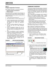
1. When the Browse Application Notes page appears,
go to the Select a Function menu and select
“Bootloader” under “Programming & Bootloaders”.
2. Click the Search button.
3. Scroll down to AN1310 and click the compressed
file icon in the “Resource Type” column.
Author: E. Schlunder
Microchip Technology Inc.
Note: If a review of the preceding features list
indicates that a different bootloader is
needed, see “Alternative References”.
AN1310
High-Speed Serial Bootloader for PIC16 and PIC18 Devices
器件 Datasheet 文档搜索
AiEMA 数据库涵盖高达 72,405,303 个元件的数据手册,每天更新 5,000 多个 PDF 文件
