Datasheet 搜索 > 微控制器 > Microchip(微芯) > PIC16F616T-I/ST 数据手册 > PIC16F616T-I/ST 开发手册 4/24 页
 器件3D模型
¥ 1.53
PIC16F616T-I/ST 开发手册 - Microchip(微芯)
制造商:
Microchip(微芯)
分类:
微控制器
封装:
TSSOP-14
描述:
PIC16 系列 128 B RAM 3.5 kB 闪存 8位 CMOS 微控制器 - TSSOP-14
Pictures:
3D模型
符号图
焊盘图
引脚图
产品图
页面导航:
原理图在P6P8
应用领域在P11P13
导航目录
PIC16F616T-I/ST数据手册
Page:
of 24 Go
若手册格式错乱,请下载阅览PDF原文件
AN1310
DS01310A-page 4 2010 Microchip Technology Inc.
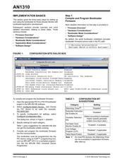
Step 3:
Program Application Firmware
More detailed information on this step is provided in:
• “Application Mode Considerations”
• “Software Design”
Once the host PIC is connected to the bootloader, the
PIC device can be read, written, erased or verified. A
sample application firmware project is installed with the
software in the path:
1. Open the appropriate project in the MPLAB IDE
software, select the desired device, configure
the settings and compile the application
firmware.
2. Open the resulting application firmware’s hex
file with the host PC’s serial bootloader
software.
3. Write the application firmware into the PIC
device by clicking the software button with the
red down arrow or by pressing the PC’s <F6>
key.
4. Direct the bootloader to start the application
firmware by clicking the software’s green “Run
Mode” button or pressing <F2> on the PC.
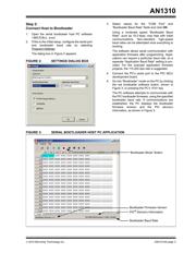
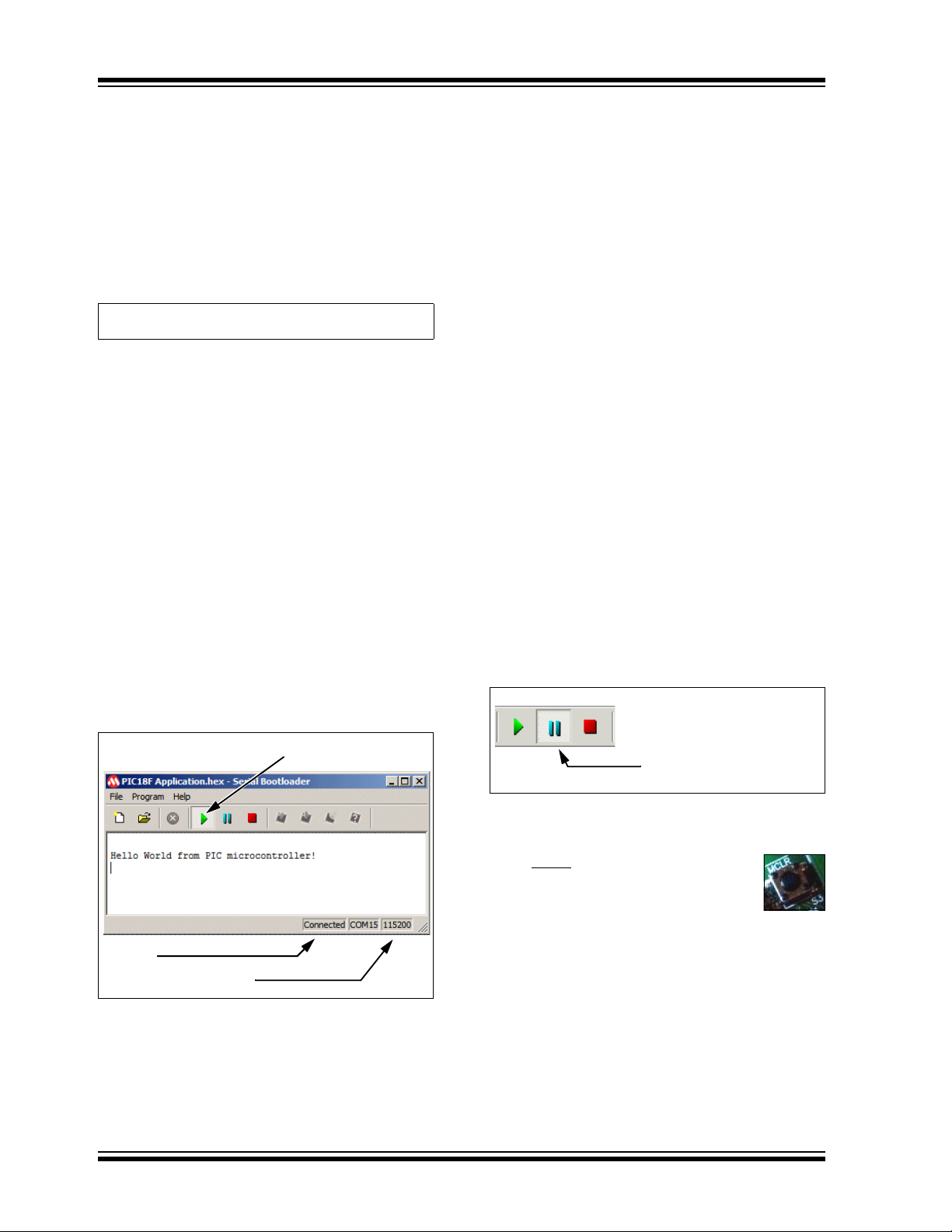
In this mode, the PC software acts as a simple
serial terminal application, as shown in Figure 4.
This allows two-way text communication with
the application firmware through the PIC
device's USART1 port.
FIGURE 4: APPLICATION RUN MODE
FIRMWARE OVERVIEW
There are two modes of firmware operation: bootloader
and application. When the microcontroller comes out of
Reset, the bootloader start-up routine decides whether
to enter the bootloader command loop (Bootloader
mode) or jump to the application entry point vector
(Application mode).
With no intervention, the Bootloader mode is entered if
either of the following conditions apply. If these
conditions do not apply, the Application mode is entered:
• If application firmware code has not been pro-
grammed into the microcontroller, the Bootloader
mode is entered.
• If the PIC device’s RX pin is at logic level low (the
RS-232 “Break” state) when the microcontroller
comes out of Reset, Bootloader mode is entered.
Bootloader mode also can be entered manually or
automatically through software or hardware.
Manual Break and Reset for Re-Entry
The host PC software enables the PIC device's RX pin
to be put into the RS-232 “Break” state. This holds the
PIC device's RX pin low, forcing the microcontroller into
Bootloader mode when it is reset.
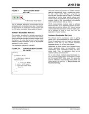
To manually enter Bootloader mode:
1. Click the software’s blue “Break/Reset Mode”
button, shown in Figure 5, or press the PC’s
<F3> key.
FIGURE 5: BREAK/RESET MODE
2. Reset the PIC device (so that the bootloader
start-up routine is executed) by doing one of the
following:
• On the development board, press the
MCLR
Reset button, shown at right
• Disconnect and reconnect the power
The device resets and the bootloader start-up
routine notices the “Break” request on the RX
pin. Bootloader mode is entered, even if applica-
tion firmware has been programmed into the
device.
3. Connect to the bootloader on the PC by clicking
the software’s red “Bootloader Mode” button,
shown in Figure 6, or pressing the PC’s <F4>
key.
C:\Microchip Solutions\Serial
Bootloader AN1310 vX.XX\PICxx Application\
Status
Application Baud Rate
“Run Mode” Button
“Break/Reset Mode” Button
器件 Datasheet 文档搜索
AiEMA 数据库涵盖高达 72,405,303 个元件的数据手册,每天更新 5,000 多个 PDF 文件
