Datasheet 搜索 > 微控制器 > Microchip(微芯) > PIC16F630T-I/ST 数据手册 > PIC16F630T-I/ST 开发手册 5/24 页

 器件3D模型
¥ 5.429
PIC16F630T-I/ST 开发手册 - Microchip(微芯)
制造商:
Microchip(微芯)
分类:
微控制器
封装:
TSSOP-14
描述:
PIC16 8位 微控制器 带1.75 KB闪存 采用14引脚TSSOP封装
Pictures:
3D模型
符号图
焊盘图
引脚图
产品图
页面导航:
原理图在P6P8
应用领域在P11P13
导航目录
PIC16F630T-I/ST数据手册
Page:
of 24 Go
若手册格式错乱,请下载阅览PDF原文件

2010 Microchip Technology Inc. DS01310A-page 5
AN1310
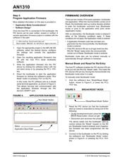
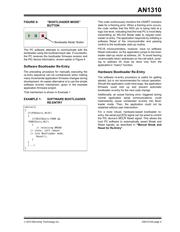
FIGURE 6: “BOOTLOADER MODE”
BUTTON
The PC software attempts to communicate with the
bootloader using the bootload baud rate. If successful,
the PC receives the bootloader firmware revision and
the PIC device information, shown earlier in Figure 4.
Software Bootloader Re-Entry
The preceding procedure for manually executing the
re-entry sequence can be cumbersome when making
many incremental application firmware changes during
development. An easier alternative is to use the simple
software re-entry mechanism, given in the example
application firmware project.
That mechanism is shown in Example 1.
EXAMPLE 1: SOFTWARE BOOTLOADER
RE-ENTRY
This code continuously monitors the USART module’s
state for a framing error. When a framing error occurs,
the code verifies that the RXD pin is being held at a
logic low level, indicating that the host PC is most likely
transmitting an RS-232 Break state to request boot-
loader re-entry. The application responds by initiating a
software Reset of the microcontroller and passing
control to the bootloader start-up routine.
PIC16 microcontrollers, however, have no software
Reset instruction, so the application jumps to the boot-
loader start-up vector at address, 0h. To avoid leaving
unremovable return addresses on the call stack, jump-
ing to address 0h must be done only from the
application’s “main()” function.
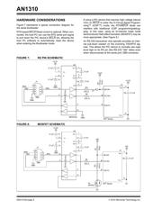
Hardware Bootloader Re-Entry
The software re-entry procedure is useful for getting
started, but is not recommended for robust operation.
Should the application code have bugs, the application
firmware could lock up and prevent automatic
bootloader re-entry for the next code change.
Additionally, an actual framing error, triggered during
normal application serial communications, could
inadvertently cause unintended re-entry into Boot-
loader mode. Then, the application could not be
restarted without user intervention.
For a more robust, hardware-based bootloader re-
entry, the serial port RTS signal can be wired to control
the PIC device’s MCLR
Reset signal. This allows the
host PC software to automatically assert Break and
Reset signals, as described in “Manual Break and
Reset for Re-Entry”.
while(1)
{
if(PIR1bits.RCIF)
{
if(RCSTAbits.FERR &&
!PORTCbits.RC7)
{
// receiving BREAK
// state, soft reboot
// into Bootloader mode.
Reset();
}
}
(...)
}
“Bootloader Mode” Button
器件 Datasheet 文档搜索
AiEMA 数据库涵盖高达 72,405,303 个元件的数据手册,每天更新 5,000 多个 PDF 文件
