Datasheet 搜索 > 微控制器 > Microchip(微芯) > PIC18LF2620-I/SP 数据手册 > PIC18LF2620-I/SP 开发手册 1/38 页
 器件3D模型
¥ 73.019
PIC18LF2620-I/SP 开发手册 - Microchip(微芯)
制造商:
Microchip(微芯)
分类:
微控制器
封装:
DIP-28
描述:
PIC18F2525/2620/4525/4620 8 位微控制器Microchip 的 PIC18F 微控制器是 Microchip 产品线中功能最强大的 8 位设备。 该系列包含的 CAN、LIN 和以太网功能是完整系列外围设备的一部分,可满足嵌入式应用和版本的需求,采用 XLP(极低功耗)技术,用于功耗为关键考量的应用。 PIC18F2525/2620/4525/4620 系列微控制器基于 Microchip 的 PIC18 体系结构,提供 31 级 硬件堆栈和 75 指令。 这些 MCU 提供高达 10 个 MIPS、多达 64 kb 的程序存储器、多达 3968 kb 的 RAM 和 124 kb 的数据 EEPROM。 板载可配置 RC 振荡器。### 微控制器功能40 MHz 最大 CPU 速度 75 指令 - 通过扩展指令集支持 83 指令 31 级硬件堆栈 内部振荡器 - 可选频率范围 8 mHz 至 31 kHz 25 个输入/输出引脚 - PIC18F2525/2620 型号 36 个输入/输出引脚 - PIC18F4525/4620 型号 nanoWatt 技术 通电重置 (POR) 通电计时器 (PWRT) 振荡器启动计时器 (OST) 掉电重置 (BOR) 延长监控计时器 (WDT) 高电压/低电压检测 (HLVD) 模块 在线串行编程 (ICSP) 在线调试 (ICD) ### 外设10 位模拟到数字转换器 (ADC) - PIC18F2525/2620 10 通道;PIC18F4525/4620 13 通道 采集、比较、PWM 模块 - PIC18F2525/2620 x 2、PIC18F4525/4620 x 1 一个增强型采集、比较、PWM 模块 - 仅 PIC18F4525/4620 型号 两个比较器 一个 8 位计时器 三个 16 位计时器 主同步串行端口 (MSSP) 模块,带有 SPI 和 I2C 增强型通用同步异步接收器发射器 (EUSART) ### PIC18 微控制器展开
Pictures:
3D模型
符号图
焊盘图
引脚图
产品图
页面导航:
原理图在P1
导航目录
PIC18LF2620-I/SP数据手册
Page:
of 38 Go
若手册格式错乱,请下载阅览PDF原文件
ã 2002 Microchip Technology Inc. DS00851B-page 1
AN851
INTRODUCTION
Among the many features built into Microchip’s
Enhanced FLASH Microcontroller devices is the capa-
bility of the program memory to self-program. This very
useful feature has been deliberately included to give
the user the ability to perform bootloading operations.
Devices like the PIC18F452 are designed with a desig-
nated “boot block”, a small section of protectable pro-
gram memory allocated specifically for bootload
firmware.
This application note demonstrates a very powerful
bootloader implementation for the PIC16F87XA and
PIC18F families of microcontrollers. The coding for the
two device families is slightly different; however, the
functionality is essentially the same. The goals of this
implementation stress a maximum performance and
functionality, while requiring a minimum of code space.
FIRMWARE
Basic Operation
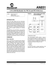
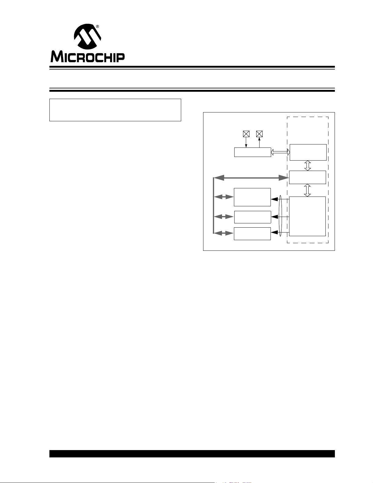
Figure 1 summarizes the essential firmware design of
the bootloader. Data is received through the USART
module, configured in Asynchronous mode for compat-
ibility with RS-232 and passed through the
transmit/receive engine. The engine filters and parses
the data, storing the information into a data buffer in
RAM. The command interpreter evaluates the com-
mand information within the buffer to determine what
should be done (i.e., Is the data written into a memory
unit? Is data read from a memory unit? Does the firm-
ware version need to be read?). Once the operation is
performed, data is passed back to the transmit/receive
engine to be transmitted back to the source, closing the
software flow control loop.
FIGURE 1: BOOTLOADER FUNCTIONAL
BLOCK DIAGRAM
COMMUNICATIONS
The microcontroller’s USART module is used to
receive and transmit data; it is configured as a UART to
be compatible with RS-232 communications. The
device can be set up in an application to bootload from
a computer through its standard serial interface. The
following communications settings are used:
• 8 data bits
•No parity
•1 STOP bit
The baud rate setting is variable depending on the
application. Baud rate selection is discussed later.
Author: Ross M. Fosler and
Rodger Richey
Microchip Technology Inc.
USART
Transmit/Receive
Engine
RAM
Buffer
Command
Interpreter
FLASH
Program
Memory
EE
Configuration
Data
Memory
TXRX
Registers
Bootloader
Control
Firmware
Data Bus
A FLASH Bootloader for PIC16 and PIC18 Devices
器件 Datasheet 文档搜索
AiEMA 数据库涵盖高达 72,405,303 个元件的数据手册,每天更新 5,000 多个 PDF 文件
