Datasheet 搜索 > 微控制器 > ST Microelectronics(意法半导体) > STM32F103C6T6A 数据手册 > STM32F103C6T6A 开发手册 4/55 页
 器件3D模型
¥ 18.695
STM32F103C6T6A 开发手册 - ST Microelectronics(意法半导体)
制造商:
ST Microelectronics(意法半导体)
分类:
微控制器
封装:
LQFP-48
描述:
STMICROELECTRONICS STM32F103C6T6A 微控制器, 32位, 电机控制, ARM 皮质-M3, 72 MHz, 32 KB, 10 KB, 48 引脚, LQFP
Pictures:
3D模型
符号图
焊盘图
引脚图
产品图
页面导航:
原理图在P24P25P26P27P28P29P30P31P32P33P34P35
应用领域在P52P55
导航目录
STM32F103C6T6A数据手册
Page:
of 55 Go
若手册格式错乱,请下载阅览PDF原文件

List of figures AN3095
4/55 Doc ID 16555 Rev 3
List of figures
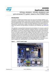
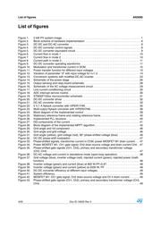
Figure 1. 3 kW PV system image. . . . . . . . . . . . . . . . . . . . . . . . . . . . . . . . . . . . . . . . . . . . . . . . . . . . . 1
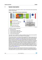
Figure 2. Block scheme of hardware implementation . . . . . . . . . . . . . . . . . . . . . . . . . . . . . . . . . . . . . 6
Figure 3. DC-DC and DC-AC converter. . . . . . . . . . . . . . . . . . . . . . . . . . . . . . . . . . . . . . . . . . . . . . . . 8
Figure 4. DC-DC converter control signals . . . . . . . . . . . . . . . . . . . . . . . . . . . . . . . . . . . . . . . . . . . . . 8
Figure 5. DC-DC converter equivalent circuit . . . . . . . . . . . . . . . . . . . . . . . . . . . . . . . . . . . . . . . . . . . 9
Figure 6. Current flow in mode 1 . . . . . . . . . . . . . . . . . . . . . . . . . . . . . . . . . . . . . . . . . . . . . . . . . . . . 10
Figure 7. Current flow in mode 2 . . . . . . . . . . . . . . . . . . . . . . . . . . . . . . . . . . . . . . . . . . . . . . . . . . . . 10
Figure 8. Current path in mode 3 . . . . . . . . . . . . . . . . . . . . . . . . . . . . . . . . . . . . . . . . . . . . . . . . . . . . 11
Figure 9. DC-DC converter operating waveforms . . . . . . . . . . . . . . . . . . . . . . . . . . . . . . . . . . . . . . . 11
Figure 10. Modulation and transformer current in DCM. . . . . . . . . . . . . . . . . . . . . . . . . . . . . . . . . . . . 12
Figure 11. Power transfer function for different input voltages . . . . . . . . . . . . . . . . . . . . . . . . . . . . . . 13
Figure 12. Variation of parameter “d” with input voltage for n=1.2. . . . . . . . . . . . . . . . . . . . . . . . . . . . 14
Figure 13. Conversion systems with modified DC-AC inverter . . . . . . . . . . . . . . . . . . . . . . . . . . . . . . 23
Figure 14. Schematic of the power stage . . . . . . . . . . . . . . . . . . . . . . . . . . . . . . . . . . . . . . . . . . . . . . 26
Figure 15. Output sensing and relay board schematic . . . . . . . . . . . . . . . . . . . . . . . . . . . . . . . . . . . . 28
Figure 16. Schematic of the AC voltage measurement circuit . . . . . . . . . . . . . . . . . . . . . . . . . . . . . . . 29
Figure 17. Line current conditioning circuit . . . . . . . . . . . . . . . . . . . . . . . . . . . . . . . . . . . . . . . . . . . . . 30
Figure 18. ADC interrupt service routine . . . . . . . . . . . . . . . . . . . . . . . . . . . . . . . . . . . . . . . . . . . . . . . 30
Figure 19. STM32F103xx microcontroller schematic. . . . . . . . . . . . . . . . . . . . . . . . . . . . . . . . . . . . . . 31
Figure 20. DC-DC converter driver . . . . . . . . . . . . . . . . . . . . . . . . . . . . . . . . . . . . . . . . . . . . . . . . . . . 32
Figure 21. DC-AC converter driver . . . . . . . . . . . . . . . . . . . . . . . . . . . . . . . . . . . . . . . . . . . . . . . . . . . 33
Figure 22. 5 V,1 A flyback converter with VIPER17HN . . . . . . . . . . . . . . . . . . . . . . . . . . . . . . . . . . . . 35
Figure 23. Multi-output flyback converter with VIPER27HN. . . . . . . . . . . . . . . . . . . . . . . . . . . . . . . . . 36
Figure 24. Block diagram of the implemented control . . . . . . . . . . . . . . . . . . . . . . . . . . . . . . . . . . . . . 39
Figure 25. Stationary reference frame and rotating reference frame . . . . . . . . . . . . . . . . . . . . . . . . . . 40
Figure 26. Implemented PLL structure. . . . . . . . . . . . . . . . . . . . . . . . . . . . . . . . . . . . . . . . . . . . . . . . . 40
Figure 27. DQ components of the current . . . . . . . . . . . . . . . . . . . . . . . . . . . . . . . . . . . . . . . . . . . . . . 41
Figure 28. Block diagram of the implemented MPPT algorithm. . . . . . . . . . . . . . . . . . . . . . . . . . . . . . 42
Figure 29. Grid angle and Vd component . . . . . . . . . . . . . . . . . . . . . . . . . . . . . . . . . . . . . . . . . . . . . . 46
Figure 30. Grid angle and grid voltage. . . . . . . . . . . . . . . . . . . . . . . . . . . . . . . . . . . . . . . . . . . . . . . . . 46
Figure 31. Grid angle (yellow), grid voltage (red), 90° phase-shifted voltage (blue) . . . . . . . . . . . . . . 46
Figure 32. DC-DC phase-shift modulation . . . . . . . . . . . . . . . . . . . . . . . . . . . . . . . . . . . . . . . . . . . . . . 47
Figure 33. Phase-shifted signals, transformer current in CCM, power MOSFET M1 drain current . . . 47
Figure 34. Power MOSFET M1- Ch1 gate signal; Ch2 drain-source voltage and drain current Ch4. . 47
Figure 35. Phase-shifted gate signals (Ch1, Ch2), primary and secondary transformer voltage
(Ch3, Ch4) . . . . . . . . . . . . . . . . . . . . . . . . . . . . . . . . . . . . . . . . . . . . . . . . . . . . . . . . . . . . . 47
Figure 36. DC-AC voltage and current in standalone mode (open-loop operation). . . . . . . . . . . . . . . 48
Figure 37. Grid voltage (blue), inverter voltage (red), injected current (green); injected power (math
function) . . . . . . . . . . . . . . . . . . . . . . . . . . . . . . . . . . . . . . . . . . . . . . . . . . . . . . . . . . . . . . . 48
Figure 38. Inverter voltage (green) and current (blue) at 800 W,PF=0.97 . . . . . . . . . . . . . . . . . . . . . . 48
Figure 39. Inverter voltage (green) and current (yellow) at 2500 W, PF . . . . . . . . . . . . . . . . . . . . . . . 48
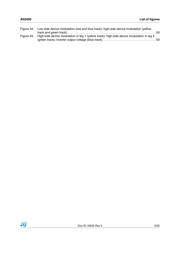
Figure 40. DC-DC converter efficiency at different input voltages . . . . . . . . . . . . . . . . . . . . . . . . . . . . 49
Figure 41. System efficiency . . . . . . . . . . . . . . . . . . . . . . . . . . . . . . . . . . . . . . . . . . . . . . . . . . . . . . . . 49
Figure 42. MOSFET M1- Ch1 gate signal, Ch2 drain-source voltage and Ch 4 drain current. . . . . . . 49
Figure 43. Phase-shifted gate signals (Ch1, Ch2), primary and secondary transformer voltage (Ch3,
Ch4) . . . . . . . . . . . . . . . . . . . . . . . . . . . . . . . . . . . . . . . . . . . . . . . . . . . . . . . . . . . . . . . . . . 49
器件 Datasheet 文档搜索
AiEMA 数据库涵盖高达 72,405,303 个元件的数据手册,每天更新 5,000 多个 PDF 文件
