Datasheet 搜索 > CAN芯片 > Microchip(微芯) > MCP2515T-I/ST 数据手册 > MCP2515T-I/ST 数据手册 5/24 页
 器件3D模型
¥ 5.332
MCP2515T-I/ST 数据手册 - Microchip(微芯)
制造商:
Microchip(微芯)
分类:
CAN芯片
封装:
TSSOP-20
描述:
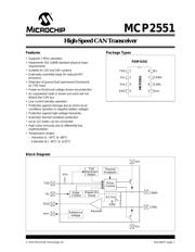
MICROCHIP MCP2515T-I/ST. 芯片, CAN总线控制器, 1MBPS, 4/3, 5.5V, TSSOP-20
Pictures:
3D模型
符号图
焊盘图
引脚图
产品图
页面导航:

导航目录
MCP2515T-I/ST数据手册
Page:
of 24 Go
若手册格式错乱,请下载阅览PDF原文件
© 2010 Microchip Technology Inc. DS21667F-page 5
MCP2551
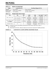
1.5 TXD Permanent Dominant
Detection
If the MCP2551 detects an extended Low state on the
TXD input, it will disable the CANH and CANL output
drivers in order to prevent the corruption of data on the
CAN bus. The drivers are disabled if TXD is Low for
more than 1.25 ms (minimum). This implies a
maximum bit time of 62.5 µs (16 kb/s bus rate),
allowing up to 20 consecutive transmitted Dominant
bits during a multiple bit error and error frame scenario.
The drivers remain disabled as long as TXD remains
Low. A rising edge on TXD will reset the timer logic and
enable the CANH and CANL output drivers.
1.6 Power-on Reset
When the device is powered on, CANH and CANL
remain in a high-impedance state until V
DD reaches the
voltage-level V
PORH. In addition, CANH and CANL will
remain in a high-impedance state if TXD is Low when
VDD reaches VPORH. CANH and CANL will become
active only after TXD is asserted High. Once powered
on, CANH and CANL will enter a high-impedance state
if the voltage level at V
DD falls below VPORL, providing
voltage brown-out protection during normal operation.
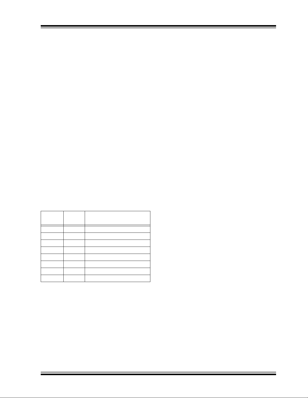
1.7 Pin Descriptions
The 8-pin pinout is listed in Table 1-3.
TABLE 1-3: MCP2551 PINOUT
1.7.1 TRANSMITTER DATA INPUT (TXD)
TXD is a TTL-compatible input pin. The data on this pin
is driven out on the CANH and CANL differential output
pins. It is usually connected to the transmitter data
output of the CAN controller device. When TXD is Low,
CANH and CANL are in the Dominant state. When TXD
is High, CANH and CANL are in the Recessive state,
provided that another CAN node is not driving the CAN
bus with a Dominant state. TXD has an internal pull-up
resistor (nominal 25 kΩ to V
DD).
1.7.2 GROUND SUPPLY (VSS)
Ground supply pin.
1.7.3 SUPPLY VOLTAGE (V
DD
)
Positive supply voltage pin.
1.7.4 RECEIVER DATA OUTPUT (RXD)
RXD is a CMOS-compatible output that drives High or
Low depending on the differential signals on the CANH
and CANL pins and is usually connected to the receiver
data input of the CAN controller device. RXD is High
when the CAN bus is Recessive and Low in the
Dominant state.
1.7.5 REFERENCE VOLTAGE (VREF)
Reference Voltage Output (defined as VDD/2).
1.7.6 CAN LOW (CANL)
The CANL output drives the Low side of the CAN
differential bus. This pin is also tied internally to the
receive input comparator.
1.7.7 CAN HIGH (CANH)
The CANH output drives the high-side of the CAN
differential bus. This pin is also tied internally to the
receive input comparator.
1.7.8 SLOPE RESISTOR INPUT (RS)
The RS pin is used to select High-Speed, Slope-Control
or Standby modes via an external biasing resistor.
Pin
Number
Pin
Name
Pin Function
1 TXD Transmit Data Input
2V
SS Ground
3V
DD Supply Voltage
4 RXD Receive Data Output
5VREF Reference Output Voltage
6 CANL CAN Low-Level Voltage I/O
7 CANH CAN High-Level Voltage I/O
8R
S Slope-Control Input
器件 Datasheet 文档搜索
AiEMA 数据库涵盖高达 72,405,303 个元件的数据手册,每天更新 5,000 多个 PDF 文件
