Datasheet 搜索 > 微控制器 > Microchip(微芯) > PIC16F610T-I/ST 数据手册 > PIC16F610T-I/ST 数据手册 34/180 页
 器件3D模型
¥ 9.717
PIC16F610T-I/ST 数据手册 - Microchip(微芯)
制造商:
Microchip(微芯)
分类:
微控制器
封装:
TSSOP-14
描述:
14引脚,基于闪存的8位CMOS微控制器 14-Pin, Flash-Based 8-Bit CMOS Microcontrollers
Pictures:
3D模型
符号图
焊盘图
引脚图
产品图
页面导航:
引脚图在P11P12P34P36P86P88P93Hot
原理图在P9P10P27P36P37P38P39P40P43P44P45P49
封装尺寸在P166
标记信息在P165
封装信息在P165P166P167P168P169
技术参数、封装参数在P46P59P61P70P71P74P110P111P112P119P159P160
应用领域在P29P96P104
电气规格在P46P59P61P70P71P74P110P111P112P119
导航目录
PIC16F610T-I/ST数据手册
Page:
of 180 Go
若手册格式错乱,请下载阅览PDF原文件
PIC16F610/616/16HV610/616
DS41288C-page 32 Preliminary © 2007 Microchip Technology Inc.
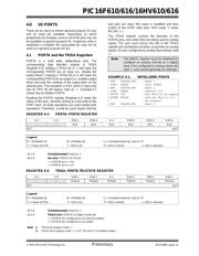
4.2 Additional Pin Functions
Every PORTA pin on the PIC16F610/616/16HV610/
616 has an interrupt-on-change option and a weak pull-
up option. The next three sections describe these
functions.
4.2.1 ANSEL REGISTER
The ANSEL register is used to configure the Input
mode of an I/O pin to analog. Setting the appropriate
ANSEL bit high will cause all digital reads on the pin to
be read as ‘0’ and allow analog functions on the pin to
operate correctly.
The state of the ANSEL bits has no affect on digital
output functions. A pin with TRIS clear and ANSEL set
will still operate as a digital output, but the Input mode
will be analog. This can cause unexpected behavior
when executing read-modify-write instructions on the
affected port.
4.2.2 WEAK PULL-UPS
Each of the PORTA pins, except RA3, has an
individually configurable internal weak pull-up. Control
bits WPUAx enable or disable each pull-up. Refer to
Register 4-4. Each weak pull-up is automatically turned
off when the port pin is configured as an output. The
pull-ups are disabled on a Power-on Reset by the
RAPU
bit of the OPTION register). A weak pull-up is
automatically enabled for RA3 when configured as
MCLR
and disabled when RA3 is an I/O. There is no
software control of the MCLR
pull-up.
4.2.3 INTERRUPT-ON-CHANGE
Each PORTA pin is individually configurable as an
interrupt-on-change pin. Control bits IOCAx enable or
disable the interrupt function for each pin. Refer to
Register 4-5. The interrupt-on-change is disabled on a
Power-on Reset.
For enabled interrupt-on-change pins, the values are
compared with the old value latched on the last read of
PORTA. The ‘mismatch’ outputs of the last read are
OR’d together to set the PORTA Change Interrupt Flag
bit (RAIF) in the INTCON register (Register 2-3).
This interrupt can wake the device from Sleep. The
user, in the Interrupt Service Routine, clears the
interrupt by:
a) Any read or write of PORTA. This will end the
mismatch condition, then,
b) Clear the flag bit RAIF.
A mismatch condition will continue to set flag bit RAIF.
Reading PORTA will end the mismatch condition and
allow flag bit RAIF to be cleared. The latch holding the
last read value is not affected by a MCLR
nor BOR
Reset. After these resets, the RAIF flag will continue to
be set if a mismatch is present.
Note: If a change on the I/O pin should occur
when any PORTA operation is being
executed, then the RAIF interrupt flag may
not get set.
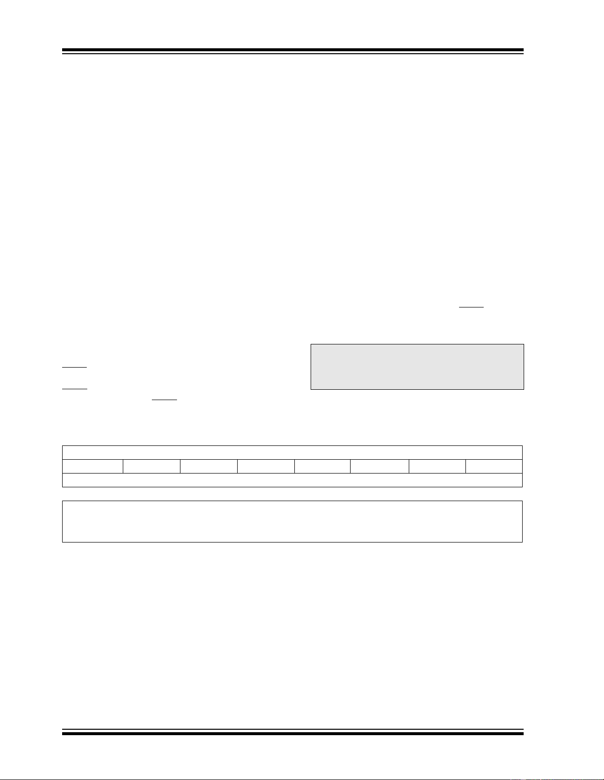
REGISTER 4-3: ANSEL: ANALOG SELECT REGISTER
R/W-1 R/W-1 R/W-1 R/W-1 R/W-1 R/W-1 R/W-1 R/W-1
ANS7 ANS6 ANS5 ANS4 ANS3 ANS2 ANS1 ANS0
bit 7 bit 0
Legend:
R = Readable bit W = Writable bit U = Unimplemented bit, read as ‘0’
-n = Value at POR ‘1’ = Bit is set ‘0’ = Bit is cleared x = Bit is unknown
bit 7-0 ANS<7:0>: Analog Select bits
Analog select between analog or digital function on pins AN<7:0>, respectively.
1 = Analog input. Pin is assigned as analog input
(1)
.
0 = Digital I/O. Pin is assigned to port or special function.
Note 1: Setting a pin to an analog input automatically disables the digital input circuitry, weak pull-ups, and
interrupt-on-change if available. The corresponding TRIS bit must be set to Input mode in order to allow
external control of the voltage on the pin.
器件 Datasheet 文档搜索
AiEMA 数据库涵盖高达 72,405,303 个元件的数据手册,每天更新 5,000 多个 PDF 文件
