Datasheet 搜索 > 32位控制器 > ST Microelectronics(意法半导体) > STM32F091VCH7 数据手册 > STM32F091VCH7 数据手册 122/128 页
 器件3D模型
¥ 35.113
STM32F091VCH7 数据手册 - ST Microelectronics(意法半导体)
制造商:
ST Microelectronics(意法半导体)
分类:
32位控制器
封装:
UFBGA-100
描述:
STMICROELECTRONICS STM32F091VCH7 微控制器, 32位, ARM 皮质-M0, 48 MHz, 256 KB, 32 KB, 100 引脚, UFBGA
Pictures:
3D模型
符号图
焊盘图
引脚图
产品图
页面导航:
引脚图在P28P29P30P31P32P33P34P35P36P37P38P39Hot
典型应用电路图在P70P71P88
原理图在P12
封装尺寸在P100P101P102P103P104P105P106P107P108P109P110P111
型号编码规则在P121P122P123P124
技术参数、封装参数在P52
电气规格在P49P50P51P52P53P54P55P56P57P58P59P60
导航目录
STM32F091VCH7数据手册
Page:
of 128 Go
若手册格式错乱,请下载阅览PDF原文件
Package information STM32F091xB STM32F091xC
122/128 DocID026284 Rev 4
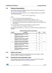
Each temperature range suffix corresponds to a specific guaranteed ambient temperature at
maximum dissipation and, to a specific maximum junction temperature.
As applications do not commonly use the STM32F091xB/xC at maximum dissipation, it is
useful to calculate the exact power consumption and junction temperature to determine
which temperature range will be best suited to the application.
The following examples show how to calculate the temperature range needed for a given
application.
Example 1: High-performance application
Assuming the following application conditions:
Maximum temperature T
Amax
= 82 °C (measured according to JESD51-2), I
DDmax
= 50
mA, V
DD
= 3.5 V, maximum 20 I/Os used at the same time in output at low level with I
OL
= 8 mA, V
OL
= 0.4 V and maximum 8 I/Os used at the same time in output at low level
with I
OL
= 20 mA, V
OL
= 1.3 V
P
INTmax
=
50 mA × 3.5 V= 175 mW
P
IOmax
=
20 × 8 mA × 0.4 V + 8 × 20 mA × 1.3 V = 272 mW
This gives: P
INTmax
= 175 mW and P
IOmax
= 272 mW:
P
Dmax
=
175
+
272 = 447 mW
Using the values obtained in Table 80 T
Jmax
is calculated as follows:
– For LQFP64, 45 °C/W
T
Jmax
= 82 °C + (45 °C/W × 447 mW) = 82 °C + 20.115 °C = 102.115 °C
This is within the range of the suffix 6 version parts (–40 < T
J
< 105 °C).
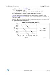
In this case, parts must be ordered at least with the temperature range suffix 6 (see
Section 8: Ordering information).
Note: With this given P
Dmax
we can find the T
Amax
allowed for a given device temperature range
(order code suffix 6 or 7).
Suffix 6: T
Amax
= T
Jmax
- (45°C/W × 447 mW) = 105-20.115 = 84.885 °C
Suffix 7: T
Amax
= T
Jmax
- (45°C/W × 447 mW) = 125-20.115 = 104.885 °C
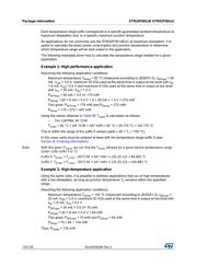
Example 2: High-temperature application
Using the same rules, it is possible to address applications that run at high temperatures
with a low dissipation, as long as junction temperature T
J
remains within the specified
range.
Assuming the following application conditions:
Maximum temperature T
Amax
= 100 °C (measured according to JESD51-2), I
DDmax
=
20 mA, V
DD
= 3.5 V, maximum 20 I/Os used at the same time in output at low level with
I
OL
= 8 mA, V
OL
= 0.4 V
P
INTmax
=
20 mA × 3.5 V= 70 mW
P
IOmax
=
20 × 8 mA × 0.4 V = 64 mW
This gives: P
INTmax
= 70 mW and P
IOmax
= 64 mW:
P
Dmax
=
70
+
64 = 134 mW
Thus: P
Dmax
= 134 mW
器件 Datasheet 文档搜索
AiEMA 数据库涵盖高达 72,405,303 个元件的数据手册,每天更新 5,000 多个 PDF 文件
