Datasheet 搜索 > 微控制器 > ST Microelectronics(意法半导体) > STM32F103R6T6ATR 数据手册 > STM32F103R6T6ATR 数据手册 93/99 页
 器件3D模型
¥ 12.768
STM32F103R6T6ATR 数据手册 - ST Microelectronics(意法半导体)
制造商:
ST Microelectronics(意法半导体)
分类:
微控制器
封装:
LQFP-64
描述:
基于ARM的低密度高性能线的32位MCU,具有16或32 KB闪存, USB , CAN ,6个定时器, 2的ADC ,6个通信接口 Low-density performance line, ARM-based 32-bit MCU with 16 or 32 KB Flash, USB, CAN, 6 timers, 2 ADCs, 6 communication interfaces
Pictures:
3D模型
符号图
焊盘图
引脚图
产品图
页面导航:
引脚图在P22P23P24P25P26P27P28Hot
典型应用电路图在P48P50P73
封装尺寸在P75P76P77P78P79P80P81P82P83P84P85P86
型号编码规则在P93P94P95
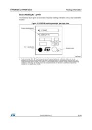
标记信息在P78P81P84P87P91
技术参数、封装参数在P32P55
电气规格在P30P31P32P33P34P35P36P37P38P39P40P41
导航目录
STM32F103R6T6ATR数据手册
Page:
of 99 Go
若手册格式错乱,请下载阅览PDF原文件

DocID15060 Rev 7 93/99
STM32F103x4, STM32F103x6 Package information
98
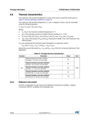
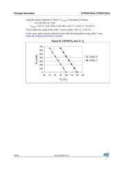
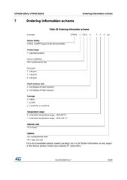
6.6.2 Selecting the product temperature range
When ordering the microcontroller, the temperature range is specified in the ordering
information scheme shown in
Table 58: Ordering information scheme.
Each temperature range suffix corresponds to a specific guaranteed ambient temperature at
maximum dissipation and, to a specific maximum junction temperature.
As applications do not commonly use the STM32F103xx at maximum dissipation, it is useful
to calculate the exact power consumption and junction temperature to determine which
temperature range will be best suited to the application.
The following examples show how to calculate the temperature range needed for a given
application.
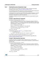
Example 1: High-performance application
Assuming the following application conditions:
Maximum ambient temperature T
Amax
= 82 °C (measured according to JESD51-2),
I
DDmax
= 50 mA, V
DD
= 3.5 V, maximum 20 I/Os used at the same time in output at low
level with I
OL
= 8 mA, V
OL
= 0.4 V and maximum 8 I/Os used at the same time in output
at low level with I
OL
= 20 mA, V
OL
= 1.3 V
P
INTmax =
50 mA × 3.5 V= 175 mW
P
IOmax = 20
× 8 mA × 0.4 V + 8 × 20 mA × 1.3 V = 272 mW
This gives: P
INTmax
= 175 mW and P
IOmax
= 272 mW:
P
Dmax =
175
+
272 = 447 mW
Thus: P
Dmax
= 447 mW
Using the values obtained in Table 57 T
Jmax
is calculated as follows:
– For LQFP64, 45 °C/W
T
Jmax
= 82 °C + (45 °C/W × 447 mW) = 82 °C + 20.115 °C = 102.115 °C
This is within the range of the suffix 6 version parts (–40 < T
J
< 105 °C).
In this case, parts must be ordered at least with the temperature range suffix 6 (see
Table 58: Ordering information scheme).
Example 2: High-temperature application
Using the same rules, it is possible to address applications that run at high ambient
temperatures with a low dissipation, as long as junction temperature T
J
remains within the
specified range.
Assuming the following application conditions:
Maximum ambient temperature T
Amax
= 115 °C (measured according to JESD51-2),
I
DDmax
= 20 mA, V
DD
= 3.5 V, maximum 20 I/Os used at the same time in output at low
level with I
OL
= 8 mA, V
OL
= 0.4 V
P
INTmax =
20 mA × 3.5 V= 70 mW
P
IOmax = 20
× 8 mA × 0.4 V = 64 mW
This gives: P
INTmax
= 70 mW and P
IOmax
= 64 mW:
P
Dmax =
70
+
64 = 134 mW
Thus: P
Dmax
= 134 mW
器件 Datasheet 文档搜索
AiEMA 数据库涵盖高达 72,405,303 个元件的数据手册,每天更新 5,000 多个 PDF 文件
