Datasheet 搜索 > 微控制器 > ST Microelectronics(意法半导体) > STM32F103R8H7 数据手册 > STM32F103R8H7 数据手册 106/117 页
 器件3D模型
¥ 69.651
STM32F103R8H7 数据手册 - ST Microelectronics(意法半导体)
制造商:
ST Microelectronics(意法半导体)
分类:
微控制器
封装:
TFBGA-64
描述:
STM32F103 系列微处理器,STMicroelectronicsSTMicroelectronics 设备 **STM32F103** Cortex-M3 芯具有 72 MHz CPU 的速度和高达 1 MB 的闪存。 包含电动机控制外围设备以及 CAN 和 USB 全速接口。 STM32 系列 ARM Cortex-M3 32 位闪存微控制器工作时具有低功率、低电压,并结合了实时功能的极佳性能。 封装类型系列可用于您的嵌入式应用。 MCU 体系结构具有一个易于使用的 STM32 平台,可用于包括电动机驱动;PC 和游戏;HVAC 和工业应用在内的应用。 32 位 RISC 引脚到引脚软件兼容 SRAM 高达 96 Kb 闪存高达 1MB 电源:2 V 至 3.6 V 温度范围:-40 至 +85 °C 或 -40 至 +105 °C ### STM32F1 系列 32 位 ARM® Cortex®-M3 微控制器,STMicroelectronics32 位闪存微控制器的 STM32 系列基于 ARM Cortex™ M3 核心的突破 - 为嵌入式应用特别开发的核心。 STM32 系列得益于 Cortex-M3 体系结构增强功能,包括为传达改进性能而设置的 Thumb-2 指令,带更好的编码密度,对中断更快的反应,所有的均和领先的工业功耗相接合。出色的实时表现 卓越功效 卓越的和新型的外围设备 最大程度的集成 跨族引脚,外围设备和软件兼容性展开
Pictures:
3D模型
符号图
焊盘图
引脚图
产品图
页面导航:
引脚图在P21P22P23P24P25P26P27P28P29P30P31P32Hot
典型应用电路图在P54P55P78
封装尺寸在P80P81P82P83P84P85P86P87P88P89P90P91
型号编码规则在P106P107P108
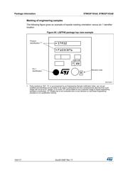
标记信息在P83P86P89P92P95P98P101P104
技术参数、封装参数在P37P60
电气规格在P35P36P37P38P39P40P41P42P43P44P45P46

导航目录
STM32F103R8H7数据手册
Page:
of 117 Go
若手册格式错乱,请下载阅览PDF原文件

Package information STM32F103x8, STM32F103xB
106/117 DocID13587 Rev 17
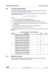
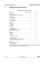
6.9.2 Selecting the product temperature range
When ordering the microcontroller, the temperature range is specified in the ordering
information scheme shown in
Table 63: Ordering information scheme.
Each temperature range suffix corresponds to a specific guaranteed ambient temperature at
maximum dissipation and, to a specific maximum junction temperature.
As applications do not commonly use the STM32F103xx at maximum dissipation, it is useful
to calculate the exact power consumption and junction temperature to determine which
temperature range will be best suited to the application.
The following examples show how to calculate the temperature range needed for a given
application.
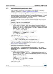
Example 1: High-performance application
Assuming the following application conditions:
Maximum ambient temperature T
Amax
= 82 °C (measured according to JESD51-2),
I
DDmax
= 50 mA, V
DD
= 3.5 V, maximum 20 I/Os used at the same time in output at low
level with I
OL
= 8 mA, V
OL
= 0.4 V and maximum 8 I/Os used at the same time in output
at low level with I
OL
= 20 mA, V
OL
= 1.3 V
P
INTmax
=
50 mA × 3.5 V= 175 mW
P
IOmax
=
20 × 8 mA × 0.4 V + 8 × 20 mA × 1.3 V = 272 mW
This gives: P
INTmax
= 175 mW and P
IOmax
= 272 mW:
P
Dmax
=
175
+
272 = 447 mW
Thus: P
Dmax
= 447 mW
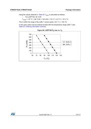
Using the values obtained in Table 62 T
Jmax
is calculated as follows:
– For LQFP100, 46 °C/W
T
Jmax
= 82 °C + (46 °C/W × 447 mW) = 82 °C + 20.6 °C = 102.6 °C
This is within the range of the suffix 6 version parts (–40 < T
J
< 105 °C).
In this case, parts must be ordered at least with the temperature range suffix 6 (see
Table 63: Ordering information scheme).
Example 2: High-temperature application
Using the same rules, it is possible to address applications that run at high ambient
temperatures with a low dissipation, as long as junction temperature T
J
remains within the
specified range.
Assuming the following application conditions:
Maximum ambient temperature T
Amax
= 115 °C (measured according to JESD51-2),
I
DDmax
= 20 mA, V
DD
= 3.5 V, maximum 20 I/Os used at the same time in output at low
level with I
OL
= 8 mA, V
OL
= 0.4 V
P
INTmax
=
20 mA × 3.5 V= 70 mW
P
IOmax
=
20 × 8 mA × 0.4 V = 64 mW
This gives: P
INTmax
= 70 mW and P
IOmax
= 64 mW:
P
Dmax
=
70
+
64 = 134 mW
Thus: P
Dmax
= 134 mW
器件 Datasheet 文档搜索
AiEMA 数据库涵盖高达 72,405,303 个元件的数据手册,每天更新 5,000 多个 PDF 文件
