Datasheet 搜索 > 二极管阵列 > VISHAY(威世) > 40CTQ045PBF 数据手册 > 40CTQ045PBF 其他数据使用手册 1/7 页

¥ 10.141
40CTQ045PBF 其他数据使用手册 - VISHAY(威世)
制造商:
VISHAY(威世)
分类:
二极管阵列
封装:
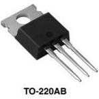
TO-220
描述:
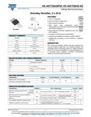
40CTQ045PbF 系列 45 V 40 A 高频 肖特基整流器 - TO-220AB
Pictures:
3D模型
符号图
焊盘图
引脚图
产品图
页面导航:
导航目录
40CTQ045PBF数据手册
Page:
of 7 Go
若手册格式错乱,请下载阅览PDF原文件
VS-40CTQ045PbF, VS-40CTQ045-N3
www.vishay.com
Vishay Semiconductors
Revision: 26-Aug-11
1
Document Number: 94212
For technical questions within your region: DiodesAmericas@vishay.com
, DiodesAsia@vishay.com, DiodesEurope@vishay.com
THIS DOCUMENT IS SUBJECT TO CHANGE WITHOUT NOTICE. THE PRODUCTS DESCRIBED HEREIN AND THIS DOCUMENT
ARE SUBJECT TO SPECIFIC DISCLAIMERS, SET FORTH AT www.vishay.com/doc?91000
Schottky Rectifier, 2 x 20 A
FEATURES
• 150 °C T
J
operation
• Very low forward voltage drop
• High frequency operation
• High purity, high temperature epoxy
encapsulation for enhanced mechanical strength
and moisture resistance
• Guard ring for enhanced ruggedness and long
term reliability
• Compliant to RoHS Directive 2002/95/EC
• Designed and qualified according to JEDEC-JESD47
• Halogen-free according to IEC 61249-2-21 definition
(-N3 only)
DESCRIPTION
This center tap Schottky rectifier has been optimized for
very low forward voltage drop, with moderate leakage. The
proprietary barrier technology allows for reliable operation
up to 150 °C junction temperature. Typical applications are
in switching power supplies, converters, freewheeling
diodes, and reverse battery protection.
PRODUCT SUMMARY
Package TO-220AB
I
F(AV)
2 x 20 A
V
R
45 V
V
F
at I
F
0.48 V
I
RM
max. 115 mA at 125 °C
T
J
max. 150 °C
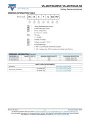
Diode variation Common cathode
E
AS
20 mJ
Anode
13
2
Base
common
cathode
2
Common
cathode
Anode
TO-220AB
MAJOR RATINGS AND CHARACTERISTICS
SYMBOL CHARACTERISTICS VALUES UNITS
I
F(AV)
Rectangular waveform 40 A
V
RRM
45 V
I
FSM
t
p
= 5 μs sine 1240 A
V
F
20 A
pk
, T
J
= 125 °C (per leg) 0.48 V
T
J
Range - 55 to 150 °C
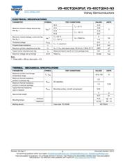
VOLTAGE RATINGS
PARAMETER SYMBOL VS-40CTQ045PbF VS-40CTQ045-N3 UNITS
Maximum DC reverse voltage V
R
45 45 V
Maximum working peak reverse voltage V
RWM
ABSOLUTE MAXIMUM RATINGS
PARAMETER SYMBOL TEST CONDITIONS VALUES UNITS
Maximum average forward current
See fig. 5
per leg
I
F(AV)
50 % duty cycle at T
C
= 116 °C, rectangular waveform
20
A
per device 40
Maximum peak one cycle non-repetitive
surge current per leg
See fig. 7
I
FSM
5 µs sine or 3 µs rect. pulse
Following any rated load
condition and with rated
V
RRM
applied
1240
10 ms sine or 6 ms rect. pulse 350
Non-repetitive avalanche energy per leg E
AS
T
J
= 25 °C, I
AS
= 3 A, L = 4.4 mH 20 mJ
Repetitive avalanche current per leg I
AR
Current decaying linearly to zero in 1 μs
Frequency limited by T
J
maximum V
A
= 1.5 x V
R
typical
3A
器件 Datasheet 文档搜索
AiEMA 数据库涵盖高达 72,405,303 个元件的数据手册,每天更新 5,000 多个 PDF 文件
