Datasheet 搜索 > Littelfuse(力特) > 60R300SXMR 数据手册 > 60R300SXMR 产品手册 1/7 页

¥ 0
60R300SXMR 产品手册 - Littelfuse(力特)
制造商:
Littelfuse(力特)
描述:
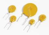
自恢复保险丝—PPTC PTC 60V 3.00A POLY RADIAL LEADS
Pictures:
3D模型
符号图
焊盘图
引脚图
产品图
页面导航:
导航目录
60R300SXMR数据手册
Page:
of 7 Go
若手册格式错乱,请下载阅览PDF原文件
©2008 Littelfuse, Inc.
Revised: October 24, 2008
POLYFUSE
®
Resettable PTCs
©2008 Littelfuse, Inc.
60R Series
Radial Leaded > 60R Series
Specifications are subject to change without notice.
Please refer to www.littelfuse.com/series/60R.html for current information.
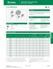
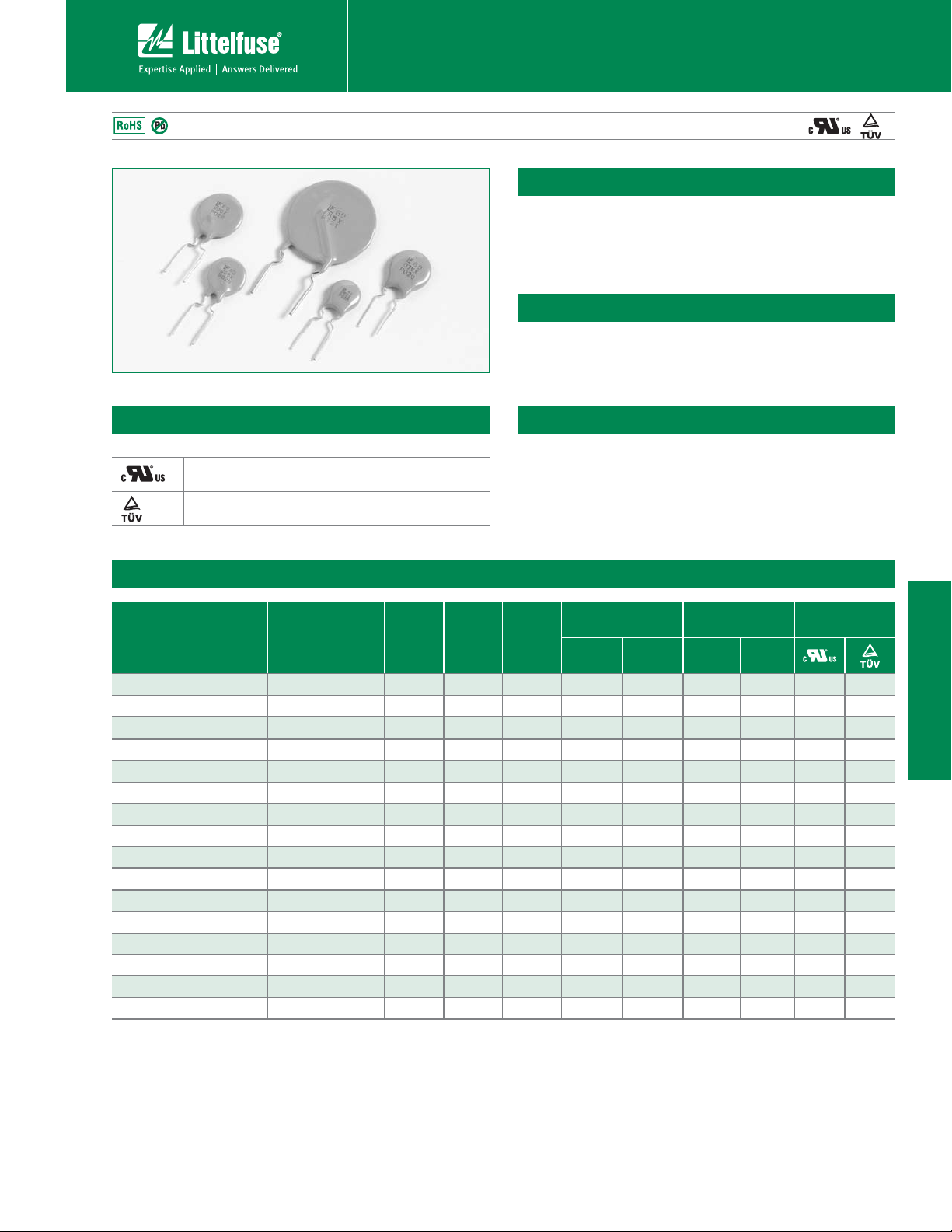
60R Series
60R Series
The 60R Series radial leaded device is designed to provide
overcurrent protection for (≤60V) applications where space
is not a concern and resettable protection
is preferred.
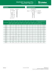
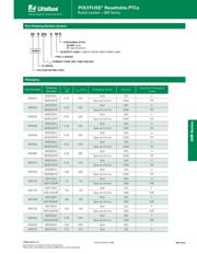
Electrical Characteristics
Part Number
I
hold
(A)
I
trip
(A)
V
max
(Vdc)
I
max
(A)
P
d
max.
(W)
Maximum Time
To Trip
Resistance
Agency
Approvals
Current
(A)
Time
(Sec.)
R
min
(Ω)
R
1max
(Ω)
60R010 0.10 0.20 60 40 0.38 0.50 4.00 2.500 7.500
XX
60R020 0.20 0.40 60 40 0.41 1.00 2.20 1.830 4.400
XX
60R025 0.25 0.50 60 40 0.45 1.25 2.50 1.250 3.000
XX
60R030 0.30 0.60 60 40 0.49 1.50 3.00 0.880 2.100
XX
60R040 0.40 0.80 60 40 0.56 2.00 3.80 0.550 1.290
XX
60R050 0.50 1.00 60 40 0.77 2.50 4.00 0.500 1.170
XX
60R065 0.65 1.30 60 40 0.88 3.25 5.30 0.310 0.720
XX
60R075 0.75 1.50 60 40 0.92 3.75 6.30 0.250 0.600
XX
60R090 0.90 1.80 60 40 0.99 4.50 7.20 0.200 0.470
XX
60R110 1.10 2.20 60 40 1.50 5.50 8.20 0.150 0.380
XX
60R135 1.35 2.70 60 40 1.70 6.75 9.60 0.120 0.300
XX
60R160 1.60 3.20 60 40 1.90 8.00 11.40 0.090 0.220
XX
60R185 1.85 3.70 60 40 2.10 9.25 12.60 0.080 0.190
XX
60R250 2.50 5.00 60 40 2.50 12.50 15.60 0.050 0.130
XX
60R300 3.00 6.00 60 40 2.80 15.00 19.80 0.040 0.100
XX
60R375 3.75 7.50 60 40 3.20 18.75 24.00 0.030 0.080
XX
Description
Features
Applications
t3P)4DPNQMJBOUBOE
lead–free
t'BTUUJNFoUPoUSJQ
t$VSFEnBNFSFUBSEBOU
epoxy polymer insulating
material meets UL 94V-0
requirements
t64#IVCTQPSUT
and peripherals
t*&&&QPSUT
t$PNQVUFSTQFSJQIFSBMT
t.PUPSQSPUFDUJPO
t(FOFSBMFMFDUSPOJDT
t"VUPNPUJWFBQQMJDBUJPOT
t*OEVTUSJBMDPOUSPMT
t5SBOTGPSNFST
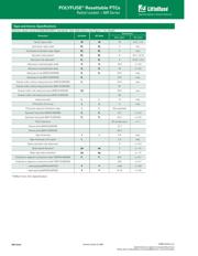
I
hold
= Hold current: maximum current device will pass without tripping in 20°C still air.
I
trip
= Trip current: minimum current at which the device will trip in 20°C still air.
V
max
= Maximum voltage device can withstand without damage at rated current (I max)
I
max
= Maximum fault current device can withstand without damage at rated voltage (V
max
)
P
d
= Power dissipated from device when in the tripped state at 20°C still air.
R
min
= Minimum resistance of device in initial (un-soldered) state.
R
typ
= Typical resistance of device in initial (un-soldered) state.
R
1max
= Maximum resistance of device at 20°C measured one hour after tripping or reflow
soldering of 260°C for 20 sec.
Caution: Operation beyond the specified rating may result in damage and possible arcing
and flame.
Agency Approvals
AGENCY AGENCY FILE NUMBER
E183209
R50119318
器件 Datasheet 文档搜索
AiEMA 数据库涵盖高达 72,405,303 个元件的数据手册,每天更新 5,000 多个 PDF 文件
