Datasheet 搜索 > 放大器、缓冲器 > ADI(亚德诺) > ADA4610-1ARJZ-R2 数据手册 > ADA4610-1ARJZ-R2 其他数据使用手册 4/18 页

¥ 19.819
ADA4610-1ARJZ-R2 其他数据使用手册 - ADI(亚德诺)
制造商:
ADI(亚德诺)
分类:
放大器、缓冲器
封装:
SOT-23-5
Pictures:
3D模型
符号图
焊盘图
引脚图
产品图
页面导航:
原理图在P8
技术参数、封装参数在P4
型号编号列表在P4

导航目录
ADA4610-1ARJZ-R2数据手册
Page:
of 18 Go
若手册格式错乱,请下载阅览PDF原文件

AN-1291 Application Note
Q: Does the memory allow the device to return to the last
stored value without an update from a microprocessor?
A: Yes. The device is automatically set to the previously stored
value each time the device is powered on. By default, the
EEPROM is factory programmed to midscale.
Q: How good is the resistance matching between Channel 1
(Ch1) and Channel 2 (Ch2) in a dual digital potentiometer?
A: The matching is typically within 0.1% to 0.2% and ±1% is
specified as a maximum mismatch. See the relevant product
data sheet for more information.
Q: How is the resistance matching, device to device?
A: Assuming the devices come from the same batch, the
resistance matching, device to device, is within ±1%.
Q: What is the resistance tolerance of digital potentiometers?
A: See the relevant product data sheet for an exact figure. If
using the potentiometer in the 3-terminal potentiometer mode
(without any series resistor), the tolerance is irrelevant because the
resistances, R
WA
and R
WB
, are ratiometric. If using the potentiometer
in the 2-terminal rheostat mode, account for the worst-case
variation.
On some nonvolatile digital potentiometers, resistance tolerance is
stored in the memory at the factory with an accuracy of 0.1%.
Thus, users can retrieve the resistance tolerance and calibrate
the system accordingly.
Q: Can I cascade, serialize, or parallel multiple digital
potentiometers to get the resistance or resolution needed?
My requirement is for a 250 Ω digital potentiometer with
approximately 1 Ω per step. I plan to use four 1 kΩ AD8403
devices in parallel with each set to nominally the same value.
A: Yes. See the AN-582 Application Note, Resolution Enhancements
of Digital Potentiometers with Multiple Devices, for more
information.
Q: How is a digital potentiometer designed? How ideal are the
wiper switches?
A: A digital potentiometer is purely a CMOS device. All switches
are large, CMOS transmission gates operated in the linear region to
yield low, uniform on resistance of the CMOS (R
DS(ON)
). All resistor
elements are polysilicon or thin film resistors.
Q: What is the temperature coefficient (TC) of the digital
potentiometer?
A: Two components make up the resistance at any given setting:
the polysilicon or thin film resistors (step resistor, R
S
), and the
CMOS switch resistor (R
SW
= 50 Ω at 5 V supply). Together,
these components add up such that
R
WB
= R
S
+ R
SW
N
AB
S
R
R
2
=
where N is the number of bits of the digital potentiometer.
The TC of the step resistor, which is published in the relevant
product data sheet, is typically −35 ppm/°C for thin film resistors
or 600 ppm/°C for polysilicon. The resistance of the switch, on
the other hand, doubles at 100°C. As a result, the overall TC is
nonlinear and it is worse off at low value codes where the switch
resistance dominates. See the TC graphs in the relevant product
data sheet for more detailed information.
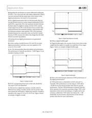
Q: What is the maximum current I can force into the digital
potentiometer?
A: The maximum current is limited by three boundaries at a given
resistance setting. The three boundaries are the maximum applied
voltage across any two of Terminal A, Terminal B, or Terminal W,
the power dissipation of the package, and the maximum current
handling capabilities of the internal switches.
Each digital potentiometer data sheet refers to this maximum
current in the Absolute Maximum Ratings section (see Table 1
for an example).
Table 1. Maximum Current Through Digital Potentiometer
Terminal: Absolute Maximum Ratings Table Example
Parameter
Rating
I
A
, I
B
, I
W
Pulsed
Frequency > 10 kHz
R
AW
= 5 kΩ and 10 kΩ ±6 mA/d
1
R
AW
= 80 kΩ ±1.5 mA/d
1
Frequency ≤ 10 kHz
R
AW
= 5 kΩ and 10 kΩ ±6 mA/√d
1
R
AW
= 80 kΩ
±1.5 mA/√d
1
Continuous
R
AW
= 5 kΩ and 10 kΩ ±6 mA
R
AW
= 80 kΩ ±1.5 mA
1
Note that d is the pulse duty factor.
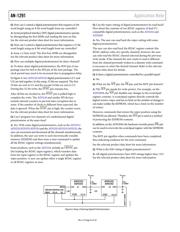
Calculating the pulsed current is dependent on the frequency. If
the frequency is less than or equal to 10 kHz, the formula is as
follows:
I
D
= I
PEAK
× √d
where:
I
D
is the maximum dc current.
I
PEAK
is the maximum peak current value for waveform.
d is the duty factor (0.1 = 10% duty cycle).
If the frequency is greater than 10 kHz, the formula is as follows:
I
D
= I
PEAK
× d
Q: Do Analog Devices digital potentiometers suffer from
leakage currents, which could affect the gain of the circuit?
A: Analog Devices digital potentiometers are manufactured
with a very low leakage analog switch process, which results in
low leakage currents. Digital potentiometers are usually
specified with a typical common-mode leakage current of 1 nA.
Rev. A | Page 4 of 18
器件 Datasheet 文档搜索
AiEMA 数据库涵盖高达 72,405,303 个元件的数据手册,每天更新 5,000 多个 PDF 文件
