Datasheet 搜索 > ADI(亚德诺) > ADA4610-4 数据手册 > ADA4610-4 其他数据使用手册 1/8 页


¥ 0
ADA4610-4 其他数据使用手册 - ADI(亚德诺)
制造商:
ADI(亚德诺)
Pictures:
3D模型
符号图
焊盘图
引脚图
产品图
ADA4610-4数据手册
Page:
of 8 Go
若手册格式错乱,请下载阅览PDF原文件

REV. B
a
AN-202
APPLICATION NOTE
One Technology Way • P.O. Box 9106 • Norwood, MA 02062-9106 • 781/329-4700 • World Wide Web Site: http://www.analog.com
An IC Amplifier User’s Guide to Decoupling, Grounding,
and Making Things Go Right for a Change
By Paul Brokaw
“There once as a breathy baboon
Who always breathed down a bassoon,
For he said "It appears
that in billions of years
I shall certainly hit on a tune”
(Sir Arthur Eddington)
This quotation seemed a proper note with which to begin
on a subject that has made monkeys of most of us at one
time or another. The struggle to find a suitable configu-
ration for system power, ground, and signal returns too
frequently degenerates into a frustrating glitch hunt.
While a strictly experimental approach can be used to
solve simple problems, a little forethought can often
prevent serious problems and provide a plan of attack if
some judicious tinkering is later required.
The subject is so fragmented that a completely general
treatment is too difficult for me to tackle. Therefore, I’d
like to state one general principle and then look a bit more
narrowly at the subject of decoupling and grounding as
it relates to integrated circuit amplifiers.
. . . Principle: Think—where the currents will flow.
I suppose this seems pretty obvious, but all of us tend to
think of the currents we’re interested in as flowing “out”
of some place and “through” some other place but often
neglect to worry how the current will find its way back to
its source. One tends to act as if all “ground” or “supply
voltage” points are equivalent and neglect (for as long
as possible) the fact that they are parts of a network of
conductors through which currents flow and develop
finite voltages.
In order to do some advance planning it is important to
consider where the currents originate and to where they
will return and to determine the effects of the resulting
voltage drops. This, in turn, requires some minimum
amount of understanding of what goes on inside the cir-
cuits being decoupled and grounded. This information
may be lacking or difficult to interpret when integrated
circuits are part of the design.
Operational amplifiers are one of the most widely used
linear lCs, and fortunately most of them fall into a few
classes, so far as the problems of power and grounding
are concerned. Although the configuration of a system
may pose formidable problems of decoupling and signal
returns, some basic methods to handle many of these
problems can be developed from a look at op amps.
OP AMPS HAVE FOUR TERMINALS
A casual look through almost any operational amplifier
text might leave the reader with the impression that an
ideal op amp has three terminals: a pair of differential
inputs and an output as shown in Figure 1. A quick review
of fundamentals, however, shows that this cannot be
the case. If the amplifier has an output voltage it must be
measured with respect to some point . . . a point to
which the amplifier has a reference. Since the ideal op
amp has infinite common-mode rejection, the inputs are
ruled out as that reference so that there must be a fourth
amplifier terminal. Another way of looking at it is that if
the amplifier is to supply output current to a load, that
current must get into the amplifier somewhere. Ideally,
no input current flows, so again the conclusion is that a
fourth terminal is required.
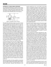
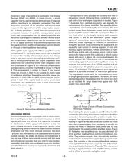
A
Figure 1. Conventional "Three Terminal" Op Amp
A common practice is to say, or indicate in a diagram,
that this fourth terminal is “ground.” Well, without get-
ting into a discussion of what “ground” may be, we can
observe that most integrated circuit op amps (and a lot
of the modular ones as well) do not have a “ground”
terminal. With these circuits the fourth terminal is one or
both of the power supply terminals. There is a tempta-
tion here to lump together both supply voltages with the
ubiquitous ground. And, to the extent that the supply
lines really do present a low impedance at all frequencies
within the amplifier bandwidth, this is probably reason-
able. When the impedance requirement is not satisfied,
however, the door is left open to a variety of problems
including noise, poor transient response, and oscillation.
器件 Datasheet 文档搜索
AiEMA 数据库涵盖高达 72,405,303 个元件的数据手册,每天更新 5,000 多个 PDF 文件
