Datasheet 搜索 > 微控制器 > Silicon Labs(芯科) > C8051F500-IMR 数据手册 > C8051F500-IMR 其他数据使用手册 4/17 页

 器件3D模型
¥ 62.504
C8051F500-IMR 其他数据使用手册 - Silicon Labs(芯科)
制造商:
Silicon Labs(芯科)
分类:
微控制器
封装:
QFN-48
描述:
8位微控制器 -MCU 50 MIPS, 64 kB, 4 kB, CAN2.0, LIN 2.1, SPI, UART, I2C, QFN48
Pictures:
3D模型
符号图
焊盘图
引脚图
产品图
页面导航:
引脚图在P11P12P13Hot
典型应用电路图在P16
原理图在P14P15
导航目录
C8051F500-IMR数据手册
Page:
of 17 Go
若手册格式错乱,请下载阅览PDF原文件

C8051F800-DK
4 Rev. 0.2
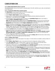
5.1.2. Getting Started With the Silicon Labs IDE
The following sections discuss how to open an example project in the IDE, build the source code, and download it
to the target device.
5.1.2.1. Running the F800_Blinky example program
The F800_Blinky example program blinks an LED on the target board.
1. Open the Silicon Labs IDE from the Start menu.
2. Select Project
Open Project to open an existing project.
3. Browse to the C:\SiLabs\MCU\Examples\C8051F80x_83x\Blinky directory (default) and select the
F800_Blinky_C.wsp project file and click Open.
4. Once the project is open, build the project by clicking on the Build/Make Project button in the toolbar or
selecting Project
Build/Make Project from the menu.
Note: After the project has been built the first time, the Build/Make Project command will only build the files
that have been changed since the previous build. To rebuild all files and project dependencies, click on the
Rebuild All button in the toolbar or select Project
Rebuild All from the menu.
5. Before connecting to the target device, several connection options may need to be set. Open the Connection
Options window by selecting Options
Connection Options... in the IDE menu. First, select the “USB Debug
Adapter” option. Next, the correct “Debug Interface” must be selected. C8051F80x-83x devices use Silicon
Labs “C2” 2-wire debug interface. Once all the selections are made, click the OK button to close the window.
6. Click the Connect button in the toolbar or select Debug
Connect from the menu to connect to the device.
7. Download the project to the target by clicking the Download Code button in the toolbar.
Note: To enable automatic downloading if the program build is successful select Enable automatic connect/
download after build in the Project
Target Build Configuration dialog. If errors occur during the build
process, the IDE will not attempt the download.
8. Click on the Go button (green circle) in the toolbar or by selecting Debug
Go from the menu to start running
the firmware. The LED on the target board will start blinking.
5.1.2.2. Creating a New Project
Use the following steps to create a new projects. Once steps 1–5 in this section are complete, continue at Step 3 in
Section 5.1.2.1.
1. Select Project
New Project to open a new project and reset all configuration settings to default.
2. Select File
New File to open an editor window. Create your source file(s) and save the file(s) with a
recognized extension, such as .c, .h, or .asm, to enable color syntax highlighting.
3. Right-click on “New Project” in the Project Window. Select Add files to project. Select files in the file browser
and click Open. Continue adding files until all project files have been added.
4. For each of the files in the Project Window that you want assembled, compiled and linked into the target build,
right-click on the file name and select Add file to build. Each file will be assembled or compiled as appropriate
(based on file extension) and linked into the build of the absolute object file.
Note: If a project contains a large number of files, the “Group” feature of the IDE can be used to organize.
Right-click on “New Project” in the Project Window. Select Add Groups to project. Add pre-defined groups or
add customized groups. Right-click on the group name and choose Add file to group. Select files to be added.
Continue adding files until all project files have been added.
5. Save the project when finished with the debug session to preserve the current target build configuration, editor
settings and the location of all open debug views. To save the project, select Project
Save Project As... from
the menu. Create a new name for the project and click on Save.
器件 Datasheet 文档搜索
AiEMA 数据库涵盖高达 72,405,303 个元件的数据手册,每天更新 5,000 多个 PDF 文件
