Datasheet 搜索 > AVX(艾维克斯) > CAN0001WM 数据手册 > CAN0001WM 其他数据使用手册 1/2 页


¥ 0
CAN0001WM 其他数据使用手册 - AVX(艾维克斯)
制造商:
AVX(艾维克斯)
Pictures:
3D模型
符号图
焊盘图
引脚图
产品图
页面导航:
导航目录
CAN0001WM数据手册
Page:
of 2 Go
若手册格式错乱,请下载阅览PDF原文件
36
CAN BUS Varistor
The CAN BUS varistor is a zinc oxide (ZnO) based ceramic semiconductor device with non-
linear voltage-current characteristics (bi-directional) similar to back-to-back Zener diodes and an
EMC capacitor in parallel (see equivalent circuit model). They have the added advantage of
greater current and energy handling capabilities as well as EMI/RFI attenuation. Devices are
fabricated by a ceramic sintering process that yields a structure of conductive ZnO grains
surrounded by electrically insulating barriers, creating varistor like behavior.
HOW TO ORDER
CAN
Style
Controlled
Area
Network
Varistor
Series
0001
Case Size
0001 = 0603 Discrete
0002 = 0405 2-Element
0004 = 0612 4-Element
0005 = 0402 Discrete
P
Termination
P = Ni/Sn Alloy
(Plated)
M = Ni/Sn Pb
(Plated)
D
Packaging Code
(Reel Size)
D = 7" reel (1,000 pcs.)
R = 7" reel (4,000 pcs.)
T = 13" reel (10,000 pcs.)
W = 7" reel (10,000 pcs.)
GENERAL DESCRIPTION
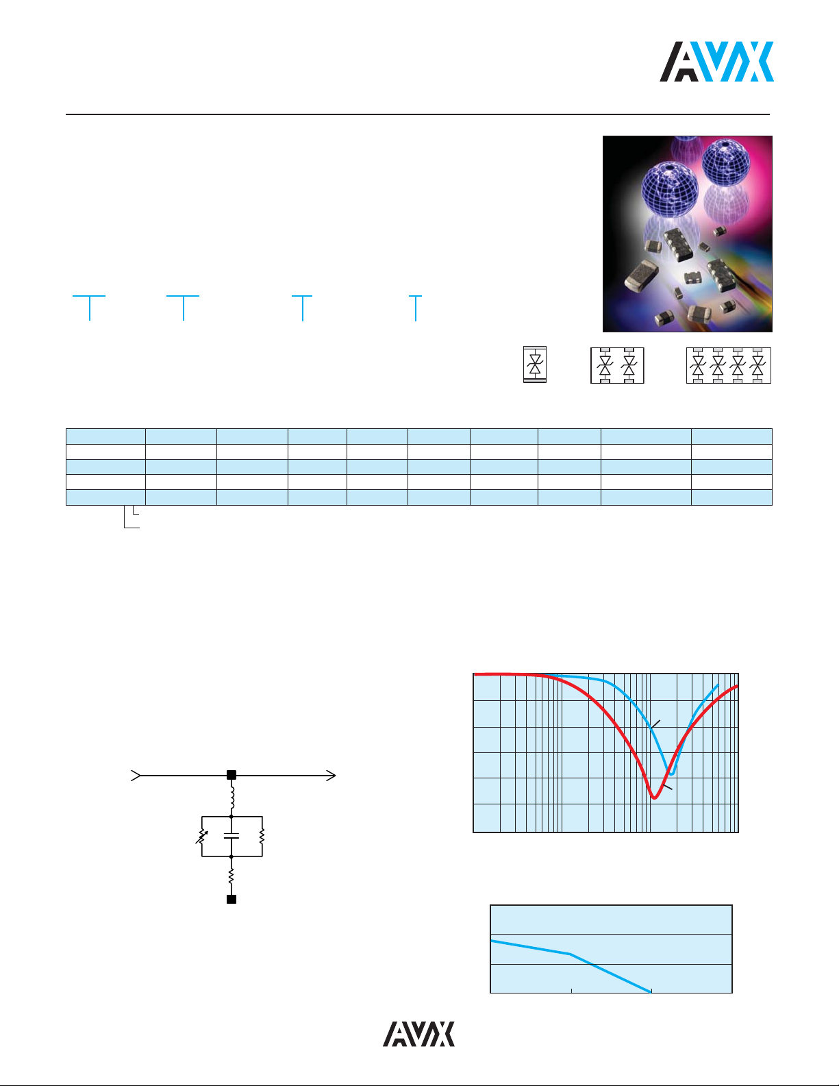
EQUIVALENT CIRCUIT MODEL
Discrete MLV Model
S
21
Curve
10000
1000
100
10
10 100 1000 10000
Pulse Duration (µS)
Peak Power (W)
Typical Pulse Rating Curve
0
-5
-10
-15
-20
-25
-30
10 100 1000
Frequency (MHz)
(dB)
10000
S21
CAN0005
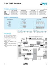
PCB
Trace
To Device
Requiring
Protection
R
V
C
R
P
R
on
L
P
Solder Pad
0402, 0603 0405 0612
Discrete Array Array
Where: R
v
= Voltage Variable resistance (per VI curve)
R
p
≥ 10
12
Ω
C = defined by voltage rating and energy level
R
on
= turn on resistance
L
p
= parallel body inductance
PERFORMANCE CHARACTERISTICS
AVX Part No. V
W
(DC) V
W
(AC) V
B
I
L
E
T
I
P
Cap. Case Size Elements
CAN0001_ _ ≤18 ≤14 120 2 0.015 4 22 0603 1
CAN0002_ _ ≤18 ≤14 70 2 0.015 4 22 0405 2
CAN0004_ _ ≤18 ≤14 100 2 0.015 4 22 0612 4
CAN0005_ _ ≤18 ≤14 21.6 5µa 0.020 1 15pF ±30% 0402 1
Termination Finish Code
Packaging Code
V
W
(DC) DC Working Voltage (V)
V
W
(AC) AC Working Voltage (V)
V
B
Typical Breakdown Voltage (V @ 1mA
DC
)
V
C
Clamping Voltage (V @ I
VC
)
I
VC
Test Current for V
C
(A, 8x20µS)
I
L
Maximum Leakage Current at the Working Voltage (µA)
E
T
Transient Energy Rating (J, 10x1000µS)
I
P
Peak Current Rating (A, 8x20µS)
Cap Maximum Capacitance (pF) @ 1 MHz and 0.5Vrms
Temp Range -55ºC to +125ºC
器件 Datasheet 文档搜索
AiEMA 数据库涵盖高达 72,405,303 个元件的数据手册,每天更新 5,000 多个 PDF 文件
