Datasheet 搜索 > 开发套件与开发板 > TI(德州仪器) > CC1010DK-433 数据手册 > CC1010DK-433 其他数据使用手册 1/2 页

¥ 0
CC1010DK-433 其他数据使用手册 - TI(德州仪器)
制造商:
TI(德州仪器)
分类:
开发套件与开发板
描述:
单芯片超低功耗RF收发器与8051兼容微控制器 Single Chip Very Low Power RF Transceiver with 8051-Compatible Microcontroller
Pictures:
3D模型
符号图
焊盘图
引脚图
产品图
CC1010DK-433数据手册
Page:
of 2 Go
若手册格式错乱,请下载阅览PDF原文件

SWRU056 Page 1 of 2
Quick Start Instructions
CC1010DK Development Kit
Introduction
The CC1010 RF transceiver and microcontroller provides a single-chip solution for a wide
range of applications. The CC1010DK Development Kit includes what you need to evaluate
the RF performance of the CC1010, develop your own software for the CC1010 and can also
be used to build a prototype of your application. An evaluation version of the Keil µVision 2 C
compiler can be downloaded from Chipcon’s or Keil’s web site.
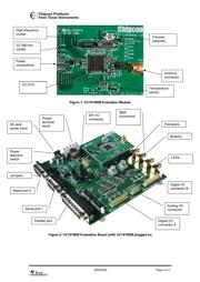
The Development Kit includes a CC1010EB Evaluation Board and two CC1010EM Evaluation
Modules. The CC1010EM contains the CC1010 chip and associated support circuits. The
CC1010EM can also operate as a stand-alone component.
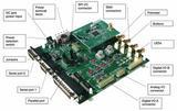
The CC1010EB serves as a motherboard for the CC1010EM Evaluation Modules. The
CC1010EB provides two serial ports, a parallel interface, buttons, LEDs, a voltage regulator,
configuration jumpers and connectors to make it easy to interface the CC1010 with Chipcon’s
Integrated Development Environment (IDE), SmartRF
®
Studio and various test equipment.
The hardware is documented in the CC1010DK User Manual, the Chipcon-supplied software
is documented in the IDE User Manual and the Keil µVision 2 compiler has its own
documentation. All of this information can be found on Chipcon’s web site. Remember to
check Chipcon’s website regularly for updates to the documentation and software.
Getting started
1. Plug a CC1010EM into the CC1010EB. Connect the CC1010EB to an external power
supply. If you are using a 4-10V supply, connect it to the 4-10V and 0V terminals on
the power connector. If you are using a 3.3V regulated supply, connect it to the 3V
and 0V terminals. Set the voltage selector switch on the CC1010EB to the correct
position.
2. If you are going to measure the current consumption of the CC1010, insert an
amperemeter between the I_IN and I_OUT terminals of the power connector. If not,
make sure that a jumper is inserted between these terminals.
3. Use the supplied parallel cable to connect the CC1010 and a PC together.
4. Make sure that you’ve installed the IDE software. This can be downloaded from
Chipcon’s web site. Run the CC1010 Flash Programmer program.
5. Click on the Browse button in the Flash Programmer, and select the adc.hex example
program. Click the Do it button.
6. A simple “Hello-world” type program is now running on the CC1010. Turn the
potmeter knob to change the speed of the blinking LEDs.
7. You can test the RF performance of the CC1010 by running the supplied SmartRF
®
Studio software. Close down the Flash Programmer and start SmartRF
®
Studio. For
details, please see the SmartRF
®
Studio User Manual.
器件 Datasheet 文档搜索
AiEMA 数据库涵盖高达 72,405,303 个元件的数据手册,每天更新 5,000 多个 PDF 文件
