Datasheet 搜索 > DC/DC转换器 > Cosel > DBS400B28 数据手册 > DBS400B28 其他数据使用手册 6/9 页

¥ 2251.087
DBS400B28 其他数据使用手册 - Cosel
制造商:
Cosel
分类:
DC/DC转换器
描述:
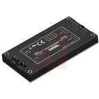
406 W 低成本 单输出 28 V 内部 AC/DC 开关电源
Pictures:
3D模型
符号图
焊盘图
引脚图
产品图
页面导航:
引脚图在P2P3Hot
导航目录
DBS400B28数据手册
Page:
of 9 Go
若手册格式错乱,请下载阅览PDF原文件
DBS
DBS-15
Table 4.1 Specification of TMP, IOG
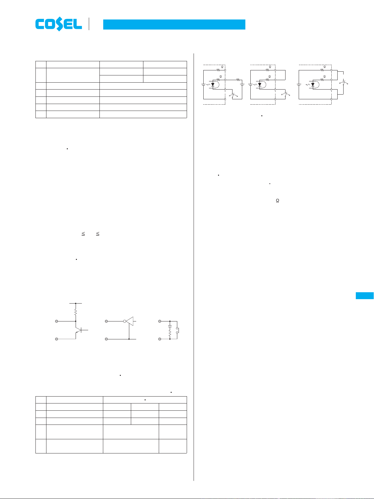
Remote ON/OFF circuit is built-in on both side of input(RC1) and
output(RC2 RC3).
Output can be controlled by either circuit.
(1) Input side remote ON/OFF(RC1)
The ground pin of input side remote ON/OFF circuit is ”-VIN” pin.
Between RC1 and -VIN: Output voltage is ON at ”Low” level or
short circuit(0 - 1.0V).
Between RC1 and -VIN: Output voltage is OFF at ”High” level or
open circuit(3.5 - 7.0V).
When RC1 is ”Low” level, fan out current is 0.3mA typ. When Vcc
is applied, use 3.5 Vcc 7V.
When remote ON/OFF function is not used, please short between
RC1 and -VIN.
When the DPA DPF series(Power factor & harmonic corrector
module) is used as a front end unit, connect between RC1 pin
and PR pin on DPA(between RC1 pin and ENA pin on DPF) for
the start-up timing of the DBS200B/400B/700B control.
4.5 Remote ON/OFF
n
n
n
Normal operation L””
35V max
Level voltage H””
10mA max
5V typ
0.5Vmax at 5mA
-S
Malfunction of inverter H””
Overheat detection L””
Normal operation H””
Maximum applicable voltage
Maximum sink current
TMP IOG
Level voltage L””
Base pin
Function
Item
6
5
4
3
2
1
No.
Fig.4.2 RC1 connection example
(2) Output side remote ON/OFF(RC2 RC3)
Table 4.2 Specification of output side remote ON/OFF(RC2 RC3)
(a) (b) (c)
Fig.4.3 RC2 RC3 connection example
Make sure that sink current of output side remote ON/OFF circuit
should be less than 12mA.
(3) Auxiliary power supply for remote ON/OFF(AUX)
AUX is built in for operating the output side remote ON/OFF
(RC2 RC3).
If AUX is not used for RC2 RC3, AUX can be used for IOG or
TMP signal output by opto coupler.
Short protection resistance(2.2k ) is built in.
Output voltage decreases as the output current increases.
(AUX voltage at open circuit: 15V max)
n
n
n
-VIN
RC1
Vcc
or
Relay
or
Transistor IC
Rc
ON
POWER
RC2
RC3
AUX
OFF
-S
typ
12V
150
2.2k
ON
POWER
RC2
RC3
AUX
OFF
-S
typ
12V
150
2.2k
typ
12V
150
2.2k
ON
POWER
RC2
RC3
AUX
OFF
-S
Open
(0.1mA max)
Short
(3mA min)
Power OFF
RC2 RC3
-S and RC2-S
Power ON L””
Fig.4.3 (c)Fig.4.3 (b)
Power ON ”H”
Power ON
Base pin
Function
Wiring method
RC2
Power ON H””
Fig.4.3 (a)
Item
5
4
3
2
1
No.
Short
(0.5V max)
Open
(0.1mA max)
4.6 Remote sensing
(1) When the remote sensing function is not in use
When the remote sensing function is not in use, it is necessary to
confirm that pins are shorted between +S & +VOUT and between
-S & -VOUT.
Wire between +S & +VOUT and between -S & -VOUT as short as
possible.
Loop wiring should be avoided.
This power supply might become unstable by the noise coming
from poor wiring.
(2) When the remote sensing function is in use
Twisted-pair wire or shield wire should be used for sensing wire.
Thick wire should be used for wiring between the power supply
and a load.
Line drop should be less than 0.5V.
Voltage between +VOUT and -VOUT should remain within the out-
put voltage adjustment range.
If the sensing patterns are short, heavy-current is drawn and the
pattern may be damaged.
The pattern disconnection can be prevented by installing the pro-
tection parts as close as a load.
n
n
n
n
n
Instruction Manual
DC-DC Converters Power Module type
DBS
DC-DC Converters Bus Converter
.
Power Module Type
meDBS.inddDPF-5me DBS indd DPF-5 2015/06/1913:19:592015/06/19 13:19:59
器件 Datasheet 文档搜索
AiEMA 数据库涵盖高达 72,405,303 个元件的数据手册,每天更新 5,000 多个 PDF 文件
