Datasheet 搜索 > Sensata Technologies(森萨塔) > DR24D03 数据手册 > DR24D03 其他数据使用手册 1/2 页

¥ 135.49
DR24D03 其他数据使用手册 - Sensata Technologies(森萨塔)
制造商:
Sensata Technologies(森萨塔)
封装:
Module
描述:
固态继电器, 3 A, 280 VAC, DIN轨安装, 螺丝, 零电压开启
Pictures:
3D模型
符号图
焊盘图
引脚图
产品图
DR24D03数据手册
Page:
of 2 Go
若手册格式错乱,请下载阅览PDF原文件
DC
Source
Control
Load
DC Relay
3
- -
4
+ +
2
1
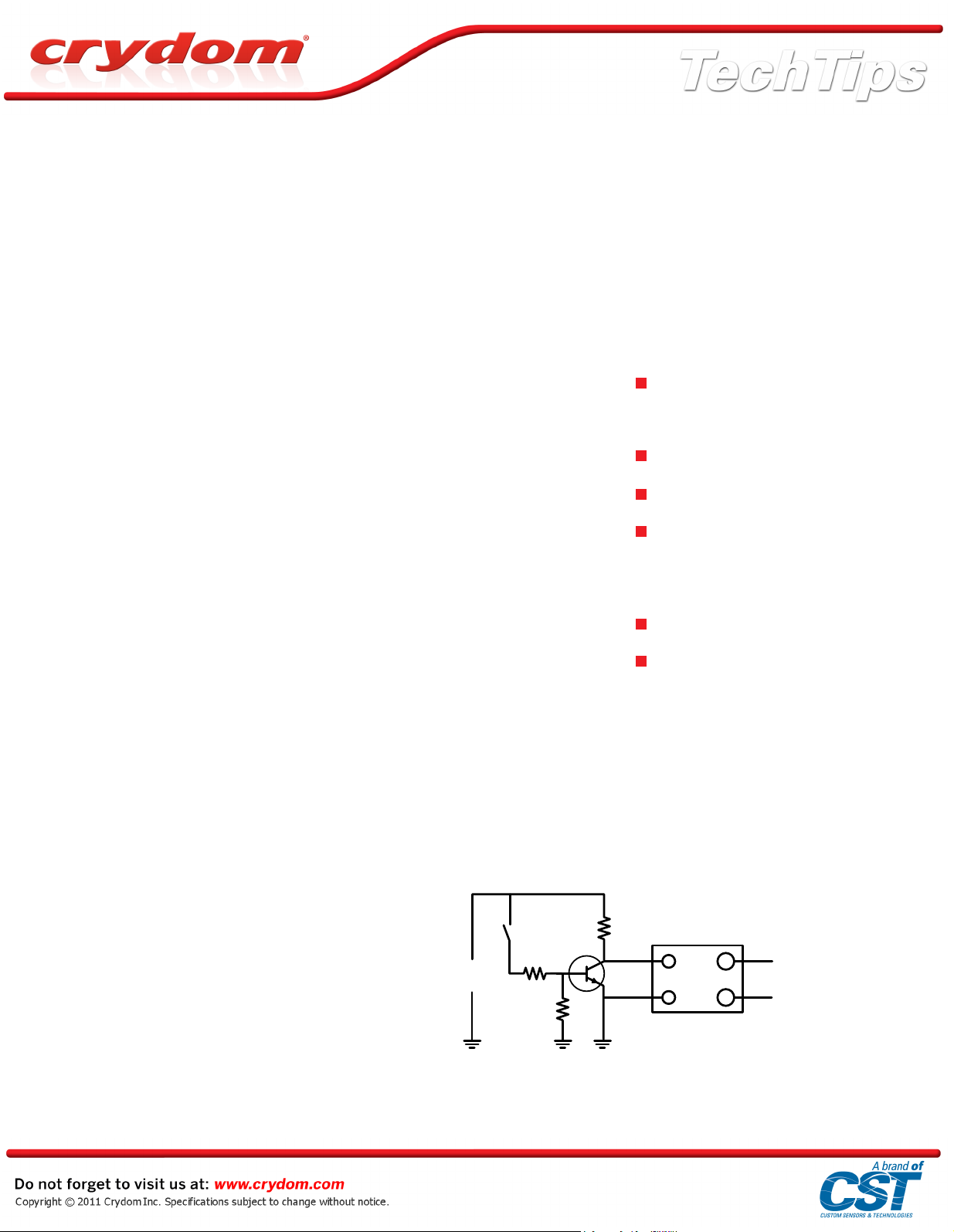
Fig 1 – NC DC relay drive
Selecting a Solid State Relay (SSR)
Page 1 of 2
Selecting a Solid State Relay
This note covers "power" rated AC
output solid state relays with
currentratings from 1 Arms to 150
Arms. Nominal AC line voltages are 120
Vrms, 240 Vrms, 380 Vrms, 480 Vrms
and 600Vrms. These nominal voltage
ratings allow a relatively wide range of
operating voltage ratings, enabling
designers to select a relay with a higher
voltage rating than would normally be
required.
The use of a solid state relay with a
rated voltage higher than the operating
line voltage should be considered in
harsh electrical environments where
high voltage transients can be
generated. Normally the maximum
transient withstand voltage for a 240
Vrms rated solid state relay is 600 volts
peak; for a 380/480Vrms rated unit, it is
1,200 volts peak. So, a 380/480 volt
rated relay used on a 120 or 240 Vrms
line allows a significant voltage safety
factor.
Printed circuit board mount solid state
relays can operate at currents from
1Arms to 10/25 Arms. The 10/25 Arms
types can be operated at 10 Arms with
natural convection cooling and up to
25Arms with forced air cooling. Above
these current ratings, a panel mount
relay should be used with
adequateheat sinking (discussed later).
Solid state relays have either a DC or
AC control. For DC control the normal
voltage range is 3-32 Vdc, but for some
families of relays, the DC control
voltage is separated into two
ranges,3-15 Vdc and 15-32 Vdc. AC
control ranges are 18-36 Vrms, 90-140
Vrms and 90-280 Vrms. All AC control
relays can also be operated on the
equivalent DC voltage (18-36 Vdc,
90-140 Vdc and 90-280 Vdc).
Most solid state relays have a normally
open output – that is, with no control
signal, the relay output is
non-conducting. Some specific types of
solid state relay have a normally closed
output, so that with no control signal the
relay output is conducting. Where a
normally closed function is required for
a DC controlled relay, and the
particular relay type that is suitable for
the application is not available with a
normally closed option, then a
simple inverter circuit (Fig 1) can be
used.
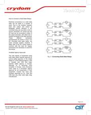
In some cases a normally open and
normally closed solid state relay will
beused to provide a change-over
function. When a break-before-make
function is required, a minimum interval
equal to one full cycle of the AC supply
frequency (16.67milliseconds for 60 Hz
and 20 milliseconds for 50 Hz) must be
provided between the removal of one
control signal and the application of the
other control signal. If this "dead"period
is not provided, especially with
inductive loads, both relays may
conduct at the same time. This
precaution also applies to applications
like AC motor reversers where, if the
wrong combination of relays is
conducting, a line-to-line short can
occur.
When selecting a Solid State Relay,
consider:
Current rating, as a general rule
consider using the relay at no more
than 70% of its rated current.
Printed circuit board or panel mount
Line voltage
Electrical environment,. i(In harsh
electrical environments, consider a
relay with an line voltage rating above
the application line voltage.)
Control voltage
Contact form
器件 Datasheet 文档搜索
AiEMA 数据库涵盖高达 72,405,303 个元件的数据手册,每天更新 5,000 多个 PDF 文件
