Datasheet 搜索 > Dallas Semiconductor(达拉斯半导体) > DS18S20+ 数据手册 > DS18S20+ 其他数据使用手册 3/23 页


¥ 11.999
DS18S20+ 其他数据使用手册 - Dallas Semiconductor(达拉斯半导体)
制造商:
Dallas Semiconductor(达拉斯半导体)
Pictures:
3D模型
符号图
焊盘图
引脚图
产品图
页面导航:
导航目录
DS18S20+数据手册
Page:
of 23 Go
若手册格式错乱,请下载阅览PDF原文件
DS18S20
3 of 23
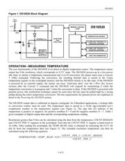
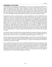
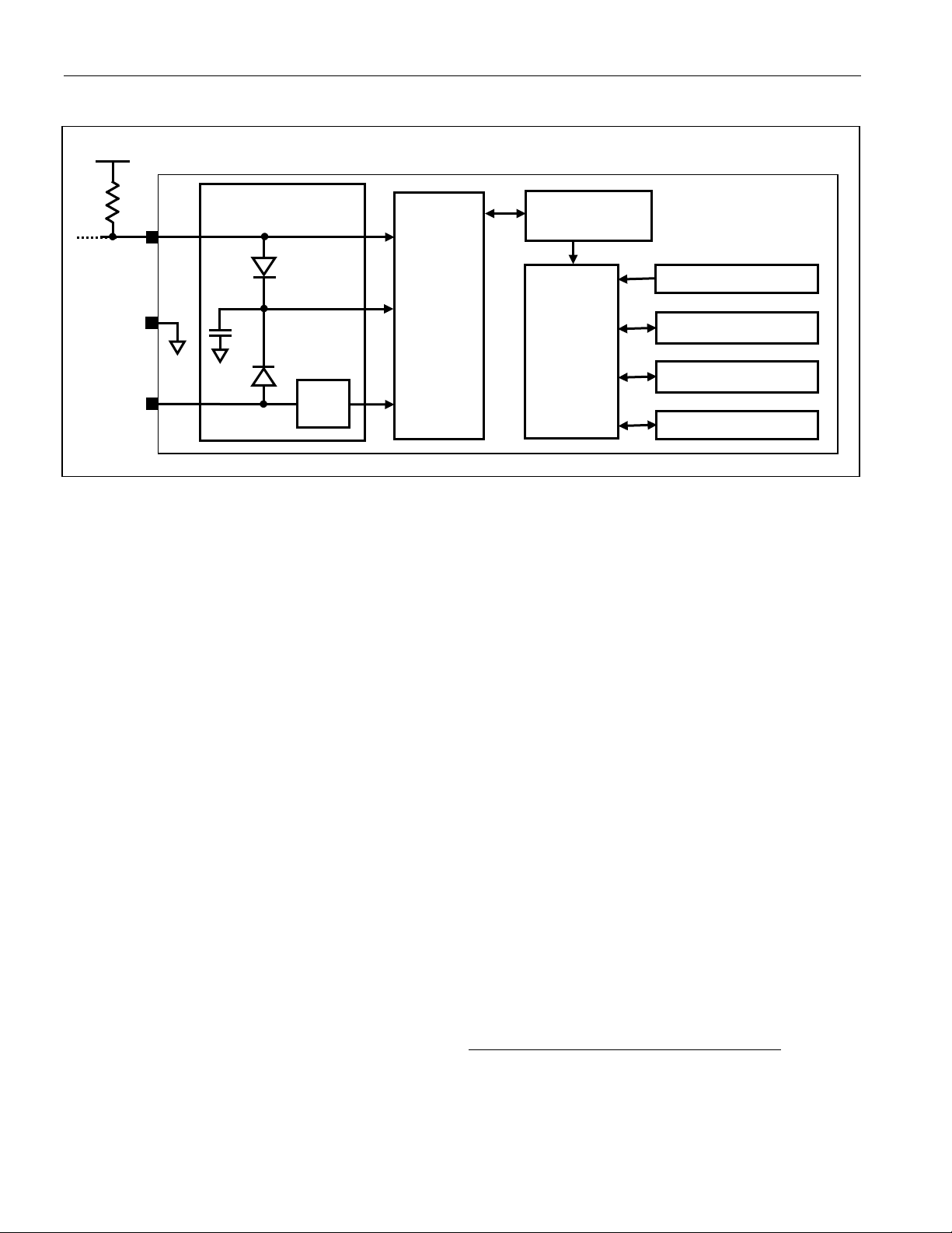
Figure 1. DS18S20 Block Diagram
OPERATION—MEASURING TEMPERATURE
The core functionality of the DS18S20 is its direct-to-digital temperature sensor. The temperature sensor
output has 9-bit resolution, which corresponds to 0.5°C steps. The DS18S20 powers-up in a low-power
idle state; to initiate a temperature measurement and A-to-D conversion, the master must issue a Convert
T [44h] command. Following the conversion, the resulting thermal data is stored in the 2-byte
temperature register in the scratchpad memory and the DS18S20 returns to its idle state. If the DS18S20
is powered by an external supply, the master can issue “read-time slots” (see the 1-Wire Bus System
section) after the Convert T command and the DS18S20 will respond by transmitting 0 while the
temperature conversion is in progress and 1 when the conversion is done. If the DS18S20 is powered with
parasite power, this notification technique cannot be used since the bus must be pulled high by a strong
pullup during the entire temperature conversion. The bus requirements for parasite power are explained in
detail in the Powering the DS18S20 section.
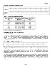
The DS18S20 output data is calibrated in degrees centigrade; for Fahrenheit applications, a lookup table
or conversion routine must be used. The temperature data is stored as a 16-bit sign-extended two’s
complement number in the temperature register (see Figure 2). The sign bits (S) indicate if the
temperature is positive or negative: for positive numbers S = 0 and for negative numbers S = 1. Table 1
gives examples of digital output data and the corresponding temperature reading.
Resolutions greater than 9 bits can be calculated using the data from the temperature, COUNT REMAIN
and COUNT PER °C registers in the scratchpad. Note that the COUNT PER °C register is hard-wired to
16 (10h). After reading the scratchpad, the TEMP_READ value is obtained by truncating the 0.5°C bit
(bit 0) from the temperature data (see Figure 2). The extended resolution temperature can then be
calculated using the following equation:
CPERCOUNT
REMAINCOUNTCPERCOUNT
READTEMPETEMPERATUR
__
___
25.0_
−
+−=
V
PU
4.7k
POWER-
SUPPLY
SENSE
64-BIT ROM
AND
1-Wire PORT
DQ
V
DD
INTERNAL V
DD
C
PP
PARASITE POWER
CIRCUIT
MEMORY CONTROL
LOGIC
SCRATCHPAD
8-BIT CRC GENERATOR
TEMPERATURE SENSOR
ALARM HIGH TRIGGER (T
H
)
REGISTER (EEPROM)
ALARM LOW TRIGGER (T
L
)
REGISTER (EEPROM)
GND
DS18S20
器件 Datasheet 文档搜索
AiEMA 数据库涵盖高达 72,405,303 个元件的数据手册,每天更新 5,000 多个 PDF 文件
