Datasheet 搜索 > 开发套件 > TI(德州仪器) > LM3553SDEV 数据手册 > LM3553SDEV 其他数据使用手册 1/5 页

¥ 1073.768
LM3553SDEV 其他数据使用手册 - TI(德州仪器)
制造商:
TI(德州仪器)
分类:
开发套件
描述:
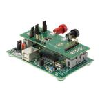
TEXAS INSTRUMENTS LM3553SDEV 评估板, LM3553, 升压稳压发光二极管驱动器
Pictures:
3D模型
符号图
焊盘图
引脚图
产品图
页面导航:
原理图在P4
应用领域在P1P5

导航目录
LM3553SDEV数据手册
Page:
of 5 Go
若手册格式错乱,请下载阅览PDF原文件

User's Guide
SNVA181E–September 2006–Revised April 2013
AN-1517 LM3658 Evaluation Kit
1 LM3658 Overview
The LM3658 is a single chip charger IC designed for handheld applications. LM3658 can safely charge
and maintain a single cell Li-Ion/Polymer battery operating off an AC wall adapter or the USB power
(VBUS). Input power source selection of USB/AC is automatic. With both power sources present, the AC
power source has priority. Charge current is programmed through an external resistor when operating
from a wall AC adapter allowing charge currents from 50 mA to 1000 mA. When the battery is charged
using USB power, charge currents of 100 mA or 500 mA are pin selectable. The termination voltage is
controlled to within ±0.35% of 4.2V. The LM3658 requires few external components and integrates internal
Power FETs, reverse current protection and current sensing. The internal power FETs are thermally
regulated to obtain the most efficient charging rate for a given ambient temperature.
The LM3658 operates in five phases: pre-qualification mode, constant-current mode, constant-voltage
mode, topoff mode and maintenance mode. Additionally, the LM3658-B charger IC operates as a linear
Regulator or in “LDO mode” when the AC wall adapter is connected and no battery is present. Optimal
battery management is obtained through the integration of thermal protection, battery temperature
measurement and a multi-mode safety timer. The LM3658 provides two open-drain outputs for LED status
indication or connection to a GPIO.
For more information, please refer to LM3658 Dual Source USB/AC Li Chemistry Charger IC for Portable
Applications (SNVS328).
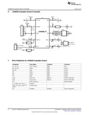
2 Evaluation Kit Overview
LM3658 evaluation kit supports complete functional evaluation of the battery charger IC. All user
accessible functions of the circuit can be controlled through jumpers. The evaluation kits are available in
three options: LM3658SDEV, LM3658SD-AEV, and LM3658SD-BEV. For detail of the various options,
please refer to order information table.
3 Getting Started
The following instructions show how to use the LM3658 evaluation kit. Please use the ESD protection
(ground cable) to prevent any unwanted damaging ESD events.
1. Connect a power supply (4.5V to 6.0V) to the “CHG-IN” and the “GND” pins. Power supply’s negative
terminal should be connected to “GND” and positive to “CHG-IN.” Alternatively, power supply can be
connected to the “USBpwr” pin and the “GND” pin.
2. Connect a Li-Ion battery pack to “BATT” and “GND” pins. The battery pack’s negative terminal should
be connected to “GND” and positive to “BATT.”
3. Check to make sure that “EN_b” pin has a jumper in place. This pulls the pin low, enabling the
LM3658.
4. Check to make sure there is a jumper in place for R7. R7 is a 5 kΩ resistor connected to the “I
SET
” pin
which will program the full-rate charge current to 500 mA.
5. Check to make sure there is a jumper in place for R8. This jumper connects a 10 kΩ resistor across
the “T
S
” pin and the “GND” pin.
6. The evaluation board is now ready for operation. Turning on the power supply will start the charge
cycle if battery is not fully charged.
All trademarks are the property of their respective owners.
1
SNVA181E–September 2006–Revised April 2013 AN-1517 LM3658 Evaluation Kit
Submit Documentation Feedback
Copyright © 2006–2013, Texas Instruments Incorporated
器件 Datasheet 文档搜索
AiEMA 数据库涵盖高达 72,405,303 个元件的数据手册,每天更新 5,000 多个 PDF 文件
