Datasheet 搜索 > NXP(恩智浦) > LPC2478FET208 数据手册 > LPC2478FET208 其他数据使用手册 5/27 页

¥ 36.18
LPC2478FET208 其他数据使用手册 - NXP(恩智浦)
制造商:
NXP(恩智浦)
封装:
TFBGA-208
描述:
单芯片16位/ 32位微; 512 kB的闪存,以太网,CAN , LCD, USB 2.0设备/主机/ OTG ,外部存储器接口 Single-chip 16-bit/32-bit micro; 512 kB flash, Ethernet, CAN, LCD, USB 2.0 device/host/OTG, external memory interface
Pictures:
3D模型
符号图
焊盘图
引脚图
产品图
页面导航:
应用领域在P26
导航目录
LPC2478FET208数据手册
Page:
of 27 Go
若手册格式错乱,请下载阅览PDF原文件
AN10675_2 © NXP B.V. 2008. All rights reserved.
Application note Rev. 02 — 13 November 2008 5 of 27
NXP Semiconductors
AN10675
Interfacing 4-wire and 5-wire resistive touchscreens to the LPC247x
Some NXP devices have a touchscreen controller included in the silicon. Such an
interface offers advantages over the software approach. It automatically detects a touch,
delays the settling times, measures both the x and y positions, and provides an interrupt
when the specified number of A/D measurements have been completed. This reduces
CPU overhead to a minimum and decreases software development time. The hardware
touch screen controller increases silicon area which does increase chip cost.
3. Interfacing to the four-wire touchscreen
3.1 Biasing requirements
The resistance of each axis of a touchscreen is typically less than 1K. The datasheet for
one particular display module, for example, lists the minimum x-direction resistance as
300 ohms and the maximum as 900 ohms. Similarly, the y-direction resistance is specified
as a minimum of 200 ohms and a maximum of 650 ohms. It is prudent then to consider the
effects of a microcontroller port pin’s output resistance when interfacing to a touchscreen.
In the case of the LPC247x family, x-position measurements are made by driving the X+
signal with a logic one output of a port pin and the X- pin with the logic zero output of a
different port pin. An A/D input, connected to the Y+ signal, is used to measure the voltage
between the point of contact and V
SS
. The Y- signal needs to be “open”. This is
accomplished by putting its respective port pin into input mode with no internal pullup or
pulldown. Y- position measurements are made in a similar manner.
The biasing and measurement requirements for each of the four wires of the touchscreen
are summarized in Table 1
.
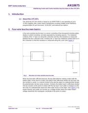
Both the X- and Y- pins have a requirement to be either open or connected to Vss, as
shown in Table 1
. A classic open drain output structure meets this requirement.
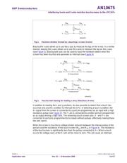
Fig 4. Touchscreen biasing for detecting a touch (4-wire)
002aad553
X− = open
X+ = input w/pullup
R
TOUCH
R
XB
R
XA
R
YB
R
YA
Y−
Y+ = open
touch sensing
Table 1. Touchscreen interface requirements
touchscreen signal
function X+ Y+ X- Y-
hardware touch
detection
digital input with
pullup
open open V
SS
read x-position voltage source voltage
measurement
Vss open
read y-position voltage
measurement
voltage source open Vss
器件 Datasheet 文档搜索
AiEMA 数据库涵盖高达 72,405,303 个元件的数据手册,每天更新 5,000 多个 PDF 文件
