Datasheet 搜索 > 接口芯片 > Microchip(微芯) > MCP2122-E/P 数据手册 > MCP2122-E/P 其他数据使用手册 5/35 页
 器件3D模型
¥ 6.897
MCP2122-E/P 其他数据使用手册 - Microchip(微芯)
制造商:
Microchip(微芯)
分类:
接口芯片
封装:
DIP-8
描述:
MICROCHIP MCP2122-E/P 芯片, 红外编码器/解码器, DIP-8
Pictures:
3D模型
符号图
焊盘图
引脚图
产品图
页面导航:
导航目录
MCP2122-E/P数据手册
Page:
of 35 Go
若手册格式错乱,请下载阅览PDF原文件
2004 Microchip Technology Inc. Preliminary DS21894A-page 5
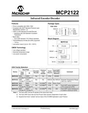
MCP2122
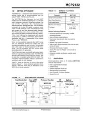
2.0 DEVICE OPERATION
The MCP2122 is a low-cost infrared encoder/decoder.
The baud rate is the same for the host UART and IR
interfaces and is determined by the frequency of the
16XCLK signal, with a maximum baud rate of
115.2 Kbaud.
The MCP2122 is made up of these functional modules:
• Clock Driver (16XCLK)
• Reset
• IR Encoder/Decoder
- IrDA Standard Encoder
- IrDA Standard Decoder
The 16XCLK circuit allows a clock input to provide the
device clock.
The Reset circuit supports an external reset signal.
The IR Encoder logic takes a data bit and converts it to
the IrDA signal according to the IrDA Standard Physical
Layer specification, while the IR Decoder logic takes
the IrDA standard signal and converts it to 8-bit data
bytes.
2.1 Power-up
As the device is powered up, there will be a voltage
range where the device will not operate properly. The
device should be reset once the device has entered the
normal operating range (from an out-of-voltage
condition). The RESET pin may then be forced high.
Other device operating parameters (such as frequency,
temperature, etc.) must also be within their operating
ranges when the device exits reset. Otherwise, the
device may not function as desired.
2.2 Device Reset
The MCP2122 is forced into the known state (RESET)
when the RESET
pin is in the low state. Once the
RESET
pin is brought to a high state, the device begins
normal operation (if the device operating parameters
are met). Table 2-1 shows the states of the output pins
while the device is in reset (RESET = Low). Table 2-2
shows the state of the output pins once the device exits
reset, RESET = L→H (device in Normal Operation
mode).
The MCP2122 has a RESET
noise filter in the RESET
input signal path. The filter will detect and ignore small
pulses.
Using the RESET pin to enter a low-power state is
discussed in Section 2.9 “Minimizing Power”.
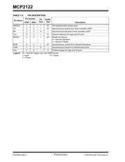
TABLE 2-1: DEFAULT OUTPUT PIN
STATES IN DEVICE RESET
TABLE 2-2: DEFAULT OUTPUT PIN
STATES AFTER DEVICE
RESET (RESET = L→H)
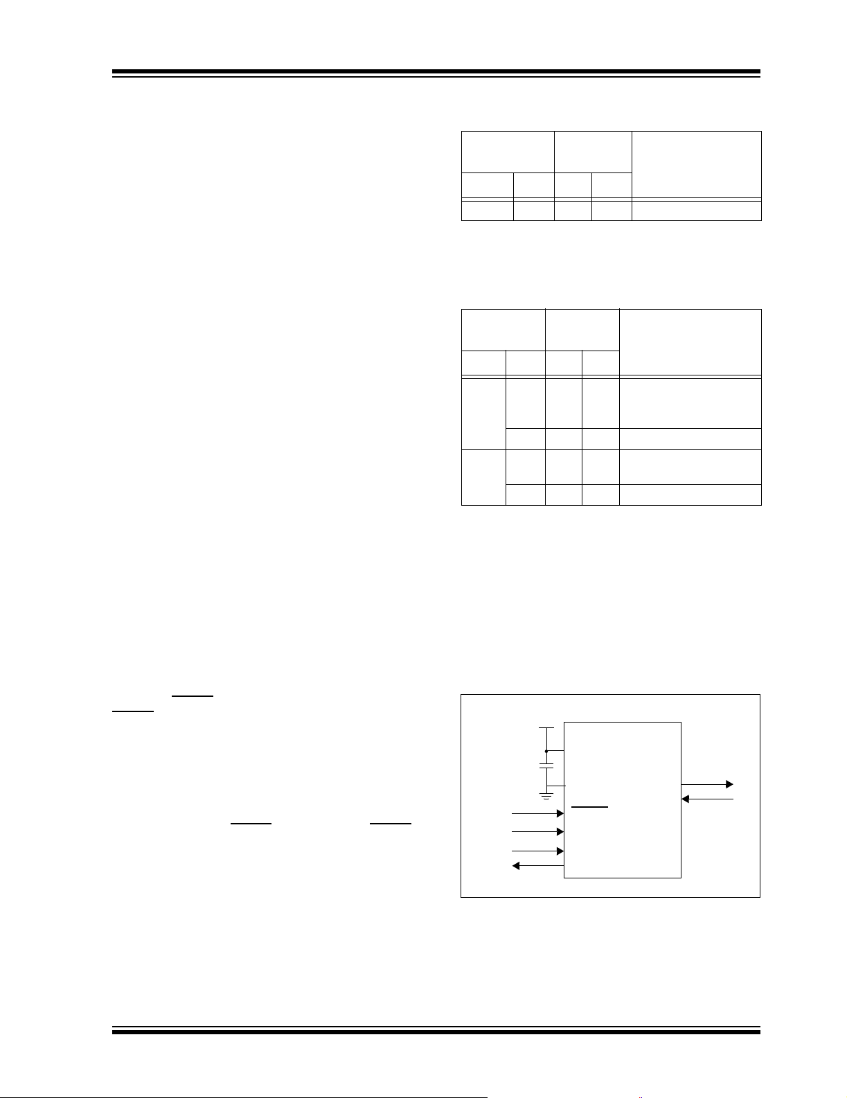
2.3 Decoupling
It is highly recommended that the MCP2122 have a
decoupling capacitor (C
BYP
). A 0.01 µF capacitor is
recommended as a starting value, but evaluation of the
best value for your circuit/layout should be done. Place
this decoupling capacitor (C
BYP
) as close to the
MCP2122 as possible ( see Figure 2-1).
FIGURE 2-1: DEVICE DECOUPLING
Input Pin
Output Pin
State
Comments
Name State RX TXIR
RESET L H L Device in Reset mode
Input Pin
Output Pin
State
Comments
Name State RX TXIR
TX L — L→H
→L
After 7 - 8 16XCLK
pulses, the TXIR pin
will pulse high.
H—L
RXIR L H→L — After 4 16XCLK pulses,
RX = L.
HH—
VDD
(bypass
capacitor)
MCP2122
VDD
RESET
VSS
16XCLK
TX
RX
TXIR
RXIR
CBYP
器件 Datasheet 文档搜索
AiEMA 数据库涵盖高达 72,405,303 个元件的数据手册,每天更新 5,000 多个 PDF 文件
