Datasheet 搜索 > 接口芯片 > Microchip(微芯) > MCP2221-I/SL 数据手册 > MCP2221-I/SL 其他数据使用手册 1/82 页
 器件3D模型
¥ 18.814
MCP2221-I/SL 其他数据使用手册 - Microchip(微芯)
制造商:
Microchip(微芯)
分类:
接口芯片
封装:
SOIC-14
描述:
MICROCHIP MCP2221-I/SL 接口桥接器, USB 至 I2C, SMBUS, UART, 3 V, 5.5 V, SOIC, 14 引脚, -40 °C
Pictures:
3D模型
符号图
焊盘图
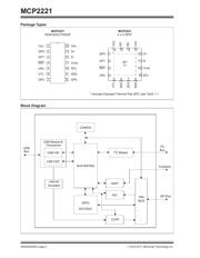
引脚图
产品图
页面导航:
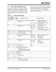
引脚图在P3P18Hot
原理图在P2
标记信息在P65
封装信息在P65P67P68P70P71P72P73P74P75P79
功能描述在P3P23P24P25P26P27P28P29P30P32P33P34
技术参数、封装参数在P61P62P63P64
导航目录
MCP2221-I/SL数据手册
Page:
of 82 Go
若手册格式错乱,请下载阅览PDF原文件

2014-2017 Microchip Technology Inc. DS20005292C-page 1
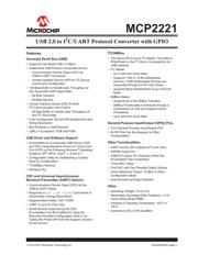
MCP2221
Features
Universal Serial Bus (USB)
• Supports Full-Speed USB (12 Mb/s)
• Implements USB Protocol Composite Device:
- Communication Device Class (CDC) for
USB-to-UART Conversion
- Human Interface Device (HID) for I
2
C Device
Control and Configuration
• 128-Byte Buffer to Handle Data Throughput at
Any Supported UART Baud Rate:
- 64-Byte Transmit
- 64-Byte Receive
• Human Interface Device (HID) for Both
I
2
C Communication and Control:
64-Byte Buffer to Handle Data Throughput at
Any I
2
C Baud Rate
• Fully-Configurable VID and PID Assignments and
String Descriptors
• Bus-Powered or Self-Powered
• USB 2.0-Compliant: TID# 40001594
USB Driver and Software Support
• Enumerates as a Composite USB Device (CDC
and HID) Using Standard Drivers for Virtual Com
Port (VCP) on the Following Windows
®
Operating
Systems: XP
®
(SP3), Vista
®
, 7, 8 and 8.1
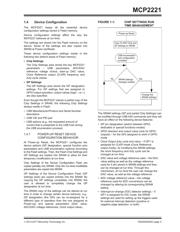
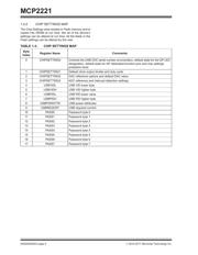
• Configuration Utility for Establishing a Custom
Boot-Up Configuration
•I
2
C/SMBus Terminal
• Windows DLL
CDC and Universal Asynchronous
Receiver/Transmitter (UART) Options
• Communications Device Class (CDC) for the
USB-to-UART Option
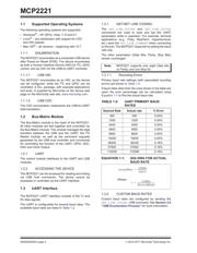
• Responds to SET LINE CODING Commands to
Dynamically Change Baud Rates
• Supports Baud Rates: 300-115200
• UART T
X and RX Pins Only
• Serial Number Used During the CDC
Enumeration Can Be Enabled by Using the
Microchip-Provided Configuration Utility or by
Calling the Proper API from the Support Libraries
for this Device
I
2
C/SMBus
• The Device Runs as an I
2
C Master. The Data to
Write/Read on the I
2
C Bus is Conveyed by the
USB Interface
•I
2
C Master
- Up to 400 kHz Clock Rate
- Supports 7-Bit or 10-Bit Addressable
Devices; 10-Bit Addressable Devices are
Supported through the PC Host Library
- Supports Block Reads/Writes of up to 65,535
Bytes
• SMBus Master
- Supports All of the SMBus Transfers
- SMBus Functionality Is Achieved through a
Combination of Chip and Support Library
Processing
- Up to 400 kHz Clock Rate
General-Purpose Input/Output (GPIO) Pins
• Four General-Purpose Input/Output Pins
• All GP Pins Can Be Assigned to Other
Functionalities
Other Functionalities
• UART Activity LED Outputs (UTX and URX)
• SSPND Output Pin
• USBCFG Output Pin (Indicates When the
Enumeration Has Completed)
• Three ADC Inputs
• One DAC with Two Possible Output Options
• Clock Reference Output: 12 MHz or Other
Configurable Values
• External Interrupt Edge Detection
Other
• Operating Voltage: 3.0 to 5.5V
• Electrostatic Discharge (ESD) Protection: > 4 kV
Human Body Model (HBM)
• Industrial (I) Operating Temperature: –40°C to
+85°C
• Automotive AEC-Q100 Qualified
USB 2.0 to I
2
C/UART Protocol Converter with GPIO
器件 Datasheet 文档搜索
AiEMA 数据库涵盖高达 72,405,303 个元件的数据手册,每天更新 5,000 多个 PDF 文件
