Datasheet 搜索 > 接口芯片 > NXP(恩智浦) > PCA9564D 数据手册 > PCA9564D 其他数据使用手册 2/39 页


¥ 32.242
PCA9564D 其他数据使用手册 - NXP(恩智浦)
制造商:
NXP(恩智浦)
分类:
接口芯片
封装:
SO-20
描述:
并行总线I2C总线控制器 Parallel bus to I2C-bus controller
Pictures:
3D模型
符号图
焊盘图
引脚图
产品图
页面导航:
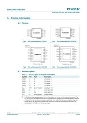
引脚图在P5P6Hot
典型应用电路图在P24
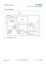
原理图在P4P6
封装尺寸在P29P30P31P32
型号编码规则在P3
焊接温度在P33P34
功能描述在P1P2P6
技术参数、封装参数在P37
应用领域在P3P37
导航目录
PCA9564D数据手册
Page:
of 39 Go
若手册格式错乱,请下载阅览PDF原文件

PCA9632 All information provided in this document is subject to legal disclaimers. © NXP B.V. 2011. All rights reserved.
Product data sheet Rev. 5 — 27 July 2011 2 of 39
NXP Semiconductors
PCA9632
4-bit Fm+ I
2
C-bus low power LED driver
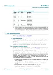
The Software Reset (SWRST) Call allows the master to perform a reset of the PCA9632
through the I
2
C-bus, identical to the Power-On Reset (POR) that initializes the registers to
their default state causing the outputs to be set high-impedance. This allows an easy and
quick way to reconfigure all device registers to the same condition.
2. Features and benefits
40 power reduction compared to PCA9633
4 LED drivers. Each output programmable at:
Off
On
Programmable LED brightness
Programmable group dimming/blinking mixed with individual LED brightness
1 MHz Fast-mode Plus I
2
C-bus interface with 30 mA high drive capability on SDA
output for driving high capacitive buses
256-step (8-bit) linear programmable brightness per LED output varying from fully off
(default) to maximum brightness using a 1.5625 kHz PWM signal in Individual
brightness mode
64-step (6-bit) linear programmable brightness for each LED output varying from fully
off (default) to maximum brightness using a 6.25 kHz PWM signal in group dimming
mode
In group dimming mode, 16-step group brightness control allows global dimming
(using a 190 Hz PWM signal) from fully off to maximum brightness (default)
256-step (8-bit) linear programmable brightness per LED output varying from fully off
(default) to maximum brightness using a 1.5625 kHz PWM signal in group blinking
mode
64-step group blinking with frequency programmable from 24 Hz to 6 Hz and
duty cycle from 0 % to 98.4 %
256-step group blinking with frequency programmable from 6 Hz to 0.09 Hz (10.73 s)
and duty cycle from 0 % to 99.6 %
Four totem pole outputs (sink 25 mA and source 10 mA at 5 V) with software
programmable open-drain LED outputs selection (default at high-impedance). No input
function.
10-pin package option provides two hardware address pins allowing four devices to
operate on the same bus
Output state change programmable on the Acknowledge or the STOP Command to
update outputs byte-by-byte or all at the same time (default to ‘Change on STOP’).
Software Reset feature (SWRST Call) allows the device to be reset through the
I
2
C-bus
400 kHz internal oscillator requires no external components
Internal power-on reset
Noise filter on SDA/SCL inputs
Edge rate control on outputs
No glitch on power-up
Supports hot insertion
Low standby current of < 1 A
Operating power supply voltage range of 2.3 V to 5.5 V
器件 Datasheet 文档搜索
AiEMA 数据库涵盖高达 72,405,303 个元件的数据手册,每天更新 5,000 多个 PDF 文件
