Datasheet 搜索 > 微控制器 > Microchip(微芯) > PIC12F1822T-I/MF 数据手册 > PIC12F1822T-I/MF 其他数据使用手册 1/24 页
 器件3D模型
¥ 6.902
PIC12F1822T-I/MF 其他数据使用手册 - Microchip(微芯)
制造商:
Microchip(微芯)
分类:
微控制器
封装:
DFN-8
描述:
3.5 KB 闪存 128 字节 RAM 32 MHz 内部振荡器6 I/0 增强型 中档内核 8DFN
Pictures:
3D模型
符号图
焊盘图
引脚图
产品图
页面导航:
功能描述在P3
导航目录
PIC12F1822T-I/MF数据手册
Page:
of 24 Go
若手册格式错乱,请下载阅览PDF原文件
2013 Microchip Technology Inc. DS00001488B-page 1
AN1488
INTRODUCTION
The 24XXXX series serial EEPROMs from Microchip
Technology are I
2
C
™
compatible and feature maximum
clock frequencies ranging from 100 kHz up to 1 MHz.
Many times when designing an application which
utilizes a serial EEPROM device, the dedicated proto-
col-specific serial port is in use by other parts of the
design. In these instances, it is required of the designer
to write software routines capable of generating the
proper signals for communicating with the EEPROM
device.
The I
2
C bit banging is a technique for serial communi-
cations using software instead of a dedicated hardware
module. This means that the code controls the state of
the MCU pins, related to all parameters of the signals:
timing, levels and synchronization.
This application note is intended to serve as a
reference for communicating with Microchip’s 24XXXX
series serial EEPROM devices, without relying on a
hardware serial port to handle the I
2
C operations.
Source code for common data transfer modes is also
provided.
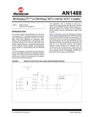
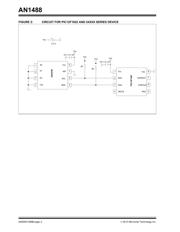
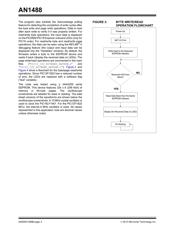
Figure 1 and Figure 2 show the hardware schematics
for the interface between Microchip’s 24XXXX devices
and PIC16LF1947/PIC12F1822 microcontrollers. The
schematics show the connections necessary between
the microcontroller and the serial EEPROM, and the
software was written assuming these connections. The
SDA pin is an open-drain terminal, and therefore
requires a pull-up resistor to V
CC (typically 10 k for
100 kHz and 2 k for 400 kHz and 1 MHz). Also, the
A0, A1 and A2 pins are tied to ground because these
set the address of the I
2
C EEPROM. The WP pin is
grounded to allow writing to the EEPROM.
FIGURE 1: CIRCUIT FOR PIC16LF1947 AND 24XXXX SERIES DEVICE
Author: Eugen Ionescu
Microchip Technology Inc.
Vcc
2K
Vss
Vcc
SCL
SDA
3
4
8
6
5
1
2
24XX256
7
WP
35
34
RC3
RC4
PIC16LF1947
64-Pin TQFP
A0
A1
A2
C4 = 0.1 uF
Vcc
Vcc
2K
Vcc
+
-
3.3 V
Bit Banging I
2
C™ on Mid-Range MCUs with the XC8 C Compiler
器件 Datasheet 文档搜索
AiEMA 数据库涵盖高达 72,405,303 个元件的数据手册,每天更新 5,000 多个 PDF 文件
