Datasheet 搜索 > 微控制器 > Microchip(微芯) > PIC12F1840-E/P 数据手册 > PIC12F1840-E/P 其他数据使用手册 1/11 页
 器件3D模型
¥ 12.034
PIC12F1840-E/P 其他数据使用手册 - Microchip(微芯)
制造商:
Microchip(微芯)
分类:
微控制器
封装:
DIP-8
描述:
PIC12F1822/1840 8 位闪存微控制器Microchip 的 PIC12 微控制器 (MCU) 是世界首个 8 引脚微控制器。 最初已经作为一次可编程 (OTP) 部件推出,此系列设备继续扩展为额外功能且添加了附加改进功能。 PIC12F1822/1840 系列微控制器基于 Microchip 具有深硬件堆栈和 49 个说明的增强型中级芯。 这些 MCU 提供高达 8 MIPS、3.5 K 字节程序内存和 128 字节数据内存。 板载可配置 RC 振荡器,精确度为 ±1%。### 特点49 个指令 16 级硬件堆栈 16 MHz 内部振荡器 – Selectable Output Range from 16 MHz to 31 kHz 6 个输入/输出引脚 1 个比较器 4 通道 10 位模拟至数字转换器 (ADC) 4 通道电容式感应 (mTouch™) 模块 两个 8 位计时器 一个 16 位计时器 1 个增强型捕获、比较 PWM (ECCP) 模块 主同步串行端口 (MSSP),带有 SPI 和 I2C EUSART 在线串行编程 (ICSP) 超低功耗 (XLP) 技术 ### PIC12F 微控制器### Microchip PIC12F 8 位 PIC® 微控制器Microchip 的 PIC12F 微控制器 (MCU) 是世界首个 8 引脚微控制器。 最初已经作为一次可编程 (OTP) 部件推出,此系列的设备将继续扩展为 Microchip 添加额外功能,进一步提高规格,并继续提供比以前更大的值。 PIC12F 成功的关键是在一个 8 引脚封装中允许六个输入/输出通道的内部 RC 振荡器。 此 RC 振荡器的更高版本可在 31kHz 和 32MHz 之间配置。展开
Pictures:
3D模型
符号图
焊盘图
引脚图
产品图
PIC12F1840-E/P数据手册
Page:
of 11 Go
若手册格式错乱,请下载阅览PDF原文件
2012-2016 Microchip Technology Inc. DS80000538E-page 1
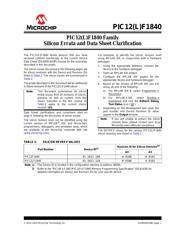
PIC12(L)F1840
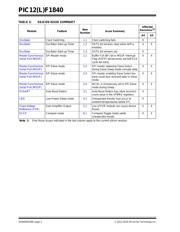
The PIC12(L)F1840 family devices that you have
received conform functionally to the current Device
Data Sheet (DS40001441F), except for the anomalies
described in this document.
The silicon issues discussed in the following pages are
for silicon revisions with the Device and Revision IDs
listed in Table 1. The silicon issues are summarized in
Table 2.
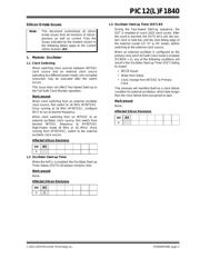
The errata described in this document will be addressed
in future revisions of the PIC12(L)F1840 silicon.
Data Sheet clarifications and corrections start on
page 8, following the discussion of silicon issues.
The silicon revision level can be identified using the
current version of MPLAB
®
IDE and Microchip’s
programmers, debuggers, and emulation tools, which
are available at the Microchip corporate web site
(www.microchip.com).
For example, to identify the silicon revision level
using MPLAB IDE in conjunction with a hardware
debugger:
1. Using the appropriate interface, connect the
device to the hardware debugger.
2. Open an MPLAB IDE project.
3. Configure the MPLAB IDE project for the
appropriate device and hardware debugger.
4. Based on the version of MPLAB IDE you are
using, do one of the following:
a) For MPLAB IDE 8, select Programmer >
Reconnect.
b) For MPLAB X IDE, select Window >
Dashboard and click the Refresh Debug
Tool Status icon ( ).
5. Depending on the development tool used, the
part number and Device Revision ID value
appear in the Output window.
The DEVREV values for the various PIC12(L)F1840
silicon revisions are shown in Table 1.
Note: This document summarizes all silicon
errata issues from all revisions of silicon,
previous as well as current. Only the
issues indicated in the last column of
Table 2 apply to the current silicon
revision (A5).
Note: If you are unable to extract the silicon
revision level, please contact your local
Microchip sales office for assistance.
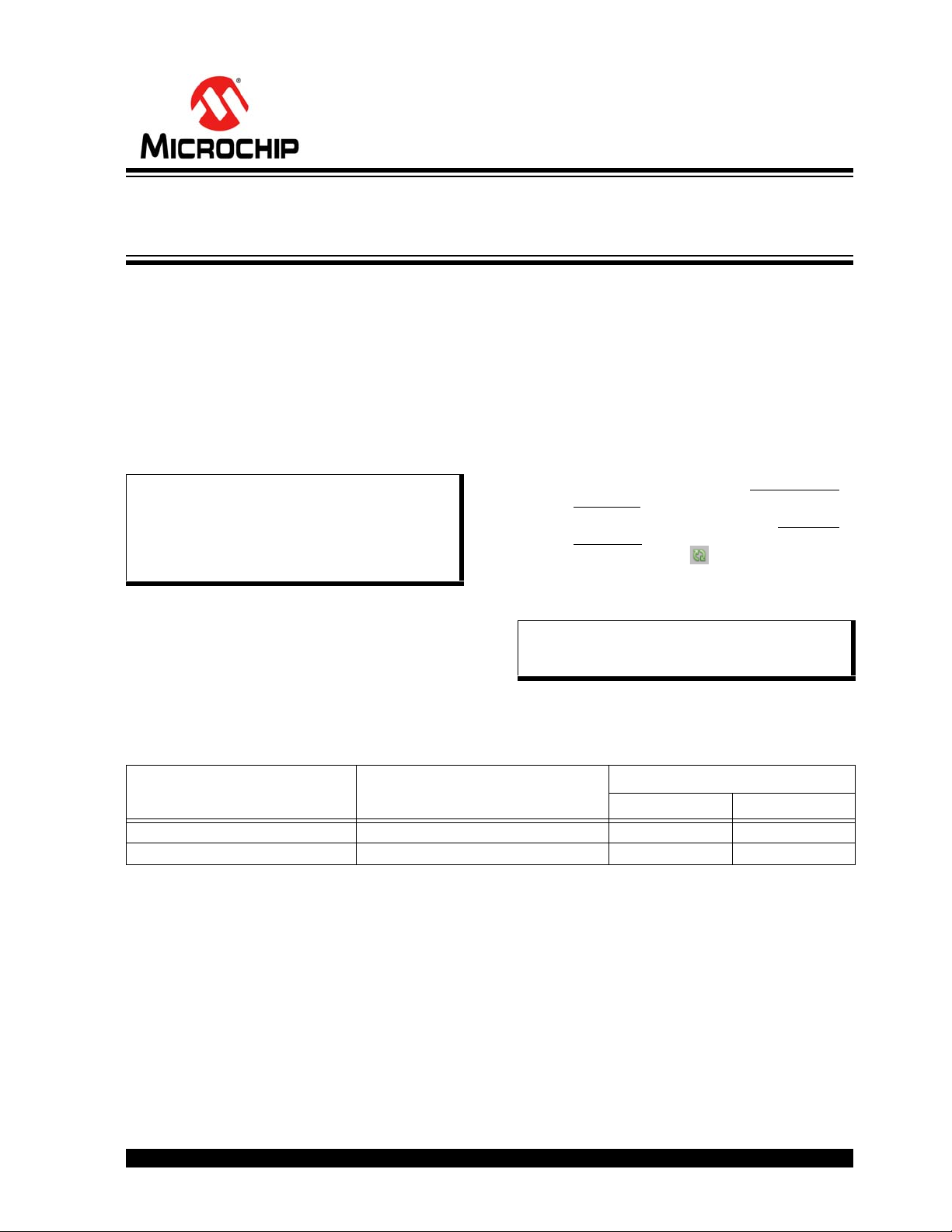
TABLE 1: SILICON DEVREV VALUES
Part Number Device ID
(1)
Revision ID for Silicon Revision
(2)
A4 A5
PIC12F1840 01 1011 100 0 0100 0 0101
PIC12LF1840 01 1011 110 0 0100 0 0101
Note 1: The Device ID is located in the configuration memory at address 8006h.
2: Refer to the “PIC16F/LF1847/PIC12F/LF1840 Memory Programming Specification” (DS41439) for
detailed information on Device and Revision IDs for your specific device.
PIC12(L)F1840 Family
Silicon Errata and Data Sheet Clarification
器件 Datasheet 文档搜索
AiEMA 数据库涵盖高达 72,405,303 个元件的数据手册,每天更新 5,000 多个 PDF 文件
