Datasheet 搜索 > 微控制器 > Microchip(微芯) > PIC16C67-10I/P 数据手册 > PIC16C67-10I/P 其他数据使用手册 1/6 页
 器件3D模型
¥ 44.746
PIC16C67-10I/P 其他数据使用手册 - Microchip(微芯)
制造商:
Microchip(微芯)
分类:
微控制器
封装:
DIP-40
描述:
8位CMOS微控制器 8-Bit CMOS Microcontrollers
Pictures:
3D模型
符号图
焊盘图
引脚图
产品图
页面导航:
技术参数、封装参数在P2
导航目录
PIC16C67-10I/P数据手册
Page:
of 6 Go
若手册格式错乱,请下载阅览PDF原文件
2001 Microchip Technology Inc. DS80098A-page 1
PIC16C67
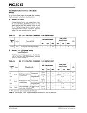
The PIC16C67 (Rev. A) parts you have received con-
form functionally to the Device Data Sheet
(DS30234D), except for the anomalies described
below.
All the problems listed here will be addressed in future
revisions of the PIC16C67 silicon.
1. Module: CCP (Compare Mode)
The Compare mode may not operate as expected
when configuring the compare match to drive the
I/O pin low (CCPxM<3:0> = 1001).
When the CCP module is changed to compare
output low (CCPxM<3:0> = 1001) from any other
non-compare CCP mode, the I/O pin will immedi-
ately be driven low, regardless of the state of the
I/O data latch. The pin will remain low when the
compare match occurs (see Table 1).
However, when the CCP module is changed to
compare output high (CCPxM<3:0> = 1000) from
any other CCP mode, the I/O pin will immediately
be driven low, regardless of the state of the I/O
data latch. The pin will be driven high when the
compare match occurs.
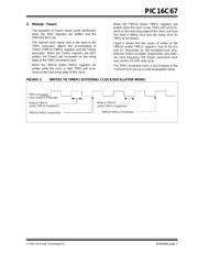
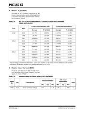
TABLE 1: COMPARE OUTPUT LOW
SWITCHING
Work around
To have the I/O pin high until the compare match
low occurs, force a compare match high to get the
I/O pin into the high state, then reconfigure the
compare match to force the I/O low, when the com-
pare condition occurs.
2. Module: SSP Module (I
2
C™ mode)
If the bus is active when the I
2
C mode is enabled,
and the next 8-bits of data on the bus match the
address of the device, then the SSP module will
generate an Acknowledge pulse.
Work around
Before enabling the I
2
C mode, ensure that the bus
is not active.
3. Module: Timer0
The TMR0 register may increment when the WDT
postscaler is switched to the Timer0 prescaler. If
TMR0 = FFh, this will cause TMR0 to overflow
(setting T0IF).
Work around
Follow the following sequence:
a) Read the 8-bit TMR0 register into the
W register
b) Clear the TMR0 register
c) Assign WDT postscaler to Timer0
d) Write W register to TMR0
CCP Mode
CCPxM<3:0> =
I/O pin
State
Change CCP to
CCPxM<3:0> =
1001 1000
0xxx
HLL
LLL
1000
HH—
LL—
1001
H—L
L—L
101x
HLL
LLL
11xx
HLL
LLL
PIC16C67 Rev. A Silicon Errata Sheet
器件 Datasheet 文档搜索
AiEMA 数据库涵盖高达 72,405,303 个元件的数据手册,每天更新 5,000 多个 PDF 文件
