Datasheet 搜索 > 微控制器 > Microchip(微芯) > PIC16C73B-04I/SP 数据手册 > PIC16C73B-04I/SP 其他数据使用手册 1/10 页
 器件3D模型
¥ 62.131
PIC16C73B-04I/SP 其他数据使用手册 - Microchip(微芯)
制造商:
Microchip(微芯)
分类:
微控制器
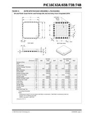
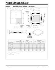
封装:
DIP-28
描述:
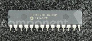
MICROCHIP PIC16C73B-04I/SP 微控制器, 8位, 一次性可编程, PIC16C7xx, 4 MHz, 7 KB, 192 Byte, 28 引脚, NDIP
Pictures:
3D模型
符号图
焊盘图
引脚图
产品图
页面导航:
引脚图在P4Hot
原理图在P2
标记信息在P3
封装信息在P3P5P6
导航目录
PIC16C73B-04I/SP数据手册
Page:
of 10 Go
若手册格式错乱,请下载阅览PDF原文件
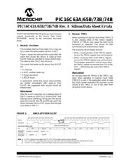
2003 Microchip Technology Inc. DS80048C-page 1
PIC16C63A/65B/73B/74B
The PIC16C63A/65B/73B/74B parts you have received
conform functionally to the Device Data Sheet
(DS30605C), except for the anomalies described
below.
1. Module: Oscillator
The Oscillator Start-up Timer delay (TOST) may not
occur when the device wakes up from SLEEP.
Figure 1 shows the start-up of the crystal after the
event that causes the device to wake-up from
SLEEP mode (as specified in Device Data Sheet).
The start-up time (T
OST) may not occur.
The events that wake-up the device from SLEEP
are:
• An interrupt
• A WDT overflow (wake-up)
• A Brown-out Reset
•A MCLR
Reset
In applications where time based measurements
are started immediately after wake-up from
SLEEP, the suggested work around should be
implemented.
Work around
After the SLEEP instruction, do a software delay of
256 T
CY (same as 1024 TOSC). At the RESET and
interrupt vector addresses, test to see if the device
woke from SLEEP (the TO
and PD bits) and if the
device did wake from SLEEP, ensure that the total
cycle delay is 256 TCY.
2. Module: TMR1
When operating in External Clock mode (TMR1CS
is set), reading either of the Timer1 registers
(TMR1H or TMR1L) may cause the timer not to
increment as expected. This occurs for both
synchronous and asynchronous inputs.
The scenarios which display this are:
• When a read operation of the TMR1H register
occurs, the TMR1L register may not increment.
• When a read operation of the TMR1L register
occurs, the TMR1H register may not increment.
This improper operation is only an issue when
the TMR1L register increments from FFh to 00h
(FFh → 00h) during the read of the TMR1L
register.
Work around
Do not read either the TMR1H or the TMR1L reg-
isters when operating in External Clock mode
(TMR1CS is set). If the application needs to read
the 16-bit counter, evaluate if this function can be
moved to the TMR0, or one of the other timer
resources on the device.
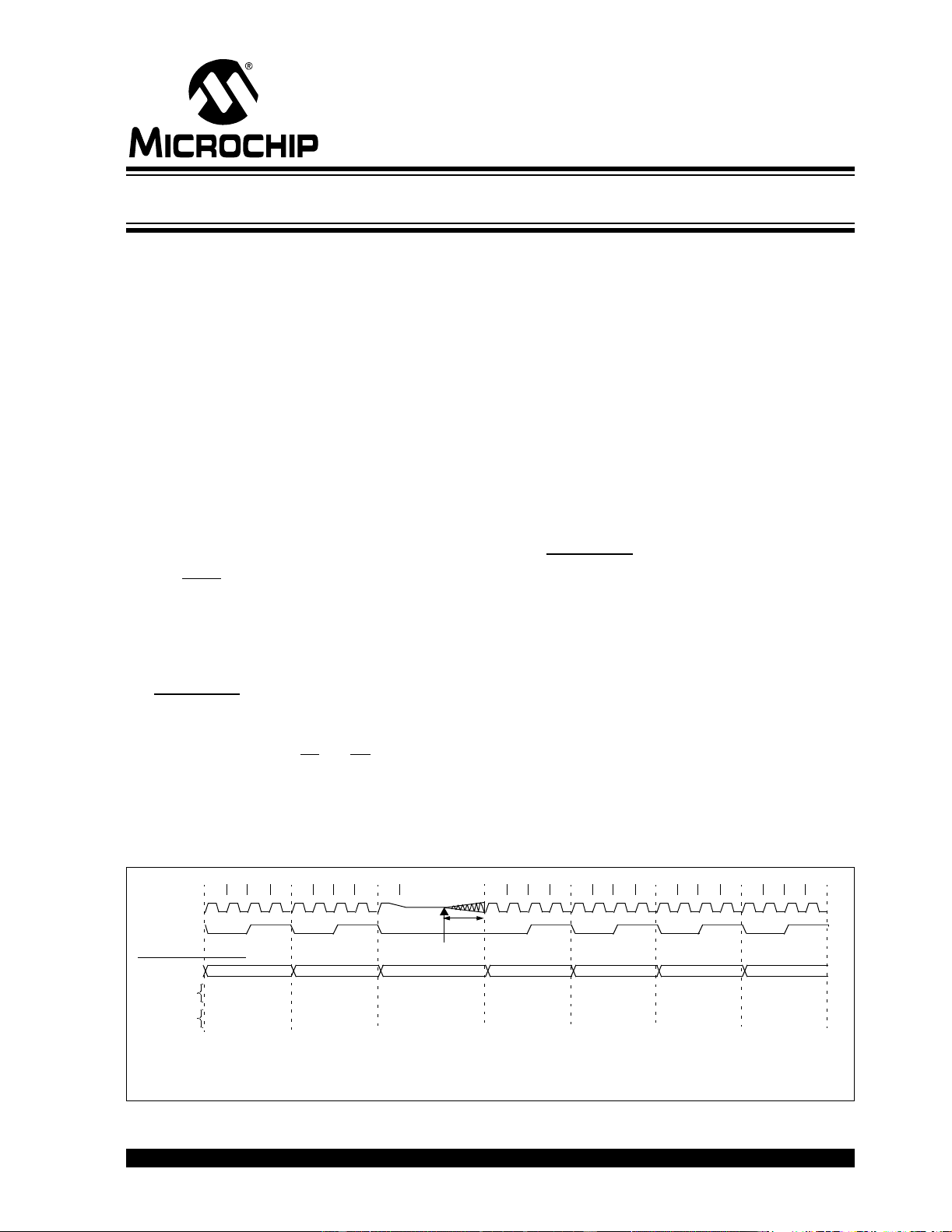
FIGURE 1: WAKE-UP FROM SLEEP
Q1 Q2 Q3 Q4 Q1 Q2 Q3 Q4 Q1 Q1 Q2 Q3 Q4 Q1 Q2 Q3 Q4 Q1 Q2 Q3 Q4 Q1 Q2 Q3 Q4
OSC1
CLKOUT
INSTRUCTION FLOW
PC
Instruction
Fetched
Instruction
Executed
PC PC+1 —
Inst(PC) = SLEEP
Inst(PC – 1)
Inst(PC + 1)
SLEEP
T
CY TCY TCY
T
OST
(1,2)
TCY
Note 1: For TOST delay to be enabled, the XT, HS or LP Oscillator mode must be selected.
2: T
OST = 1024 TOSC. This delay may not occur, and every valid clock edge will generate internal device clocks.
3: CLKOUT is not available in these Oscillator modes but shown here for timing reference.
Wake-up Event Occurs
PIC16C63A/65B/73B/74B Rev. A Silicon/Data Sheet Errata
器件 Datasheet 文档搜索
AiEMA 数据库涵盖高达 72,405,303 个元件的数据手册,每天更新 5,000 多个 PDF 文件
