Datasheet 搜索 > 微控制器 > Microchip(微芯) > PIC16F872T-E/SS 数据手册 > PIC16F872T-E/SS 其他数据使用手册 1/6 页
 器件3D模型
¥ 22.674
PIC16F872T-E/SS 其他数据使用手册 - Microchip(微芯)
制造商:
Microchip(微芯)
分类:
微控制器
封装:
SSOP-28
描述:
8位微控制器 -MCU 3.5KB 128 RAM 22 I/O
Pictures:
3D模型
符号图
焊盘图
引脚图
产品图
页面导航:
技术参数、封装参数在P1
电气规格在P1


导航目录
PIC16F872T-E/SS数据手册
Page:
of 6 Go
若手册格式错乱,请下载阅览PDF原文件

2001 Microchip Technology Inc. DS80076B-page 1
PIC16F872
The PIC16F872 Rev. A2 parts you have received con-
form functionally to the Device Data Sheet
(DS30221A), except for the anomalies described
below.
All the problems listed here will be addressed in future
revisions of the PIC16F872 silicon.
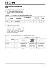
1. Module: Electrical Specifications
The supply voltage specification has not yet met
the design target (data sheet specification). The
specification for these devices is shown in Table 1.
2. Programming Issues
Problems may be experienced when programming
devices with date codes earlier than and including
0034NNN. These devices are shipped with Low
Voltage In-Circuit Serial Programming (ICSP)
(LVP) enabled. In this mode, the I/O pin, RB3, is
used to place the device in Programming mode.
Most programmers will leave this pin floating,
which may cause the device to enter Programming
mode before MCLR
has been released from
ground. This sequence of events prevents the
device from entering Programming mode properly.
Work around
Connect a 10 kΩ resistor from pin RB3 to ground.
This resistor can be placed in the programming
socket when the device is programmed in a
programmer.
When programming, using ICSP with the device
mounted on the target board, pin RB3 must be
pulled or driven low during programming.
If Low Voltage ICSP Programming is not required
in the application, it should be disabled. All future
programming cycles will not require pin RB3 to be
pulled, or driven low after LVP is disabled.
3. Module: Timer1
When Timer1 is running in Asynchronous mode
and then disabled, data in the Timer1 register
(TMR1) may become corrupted. Corruption occurs
when the timer enable is turned off at the same
instant that a ripple carry occurs in the timer
module.
This issue only occurs in asynchronous operation.
In synchronous operation, the relevant signals are
latched with the CPU clock and the problem condi-
tion does not arise.
Work around
When Timer1 is configured to operate as an asyn-
chronous counter, care must be taken that there is
no incoming pulse while the module is being
turned off. If an incoming pulse arrives while
Timer1 is being turned off, the value of register
TMR1 may become corrupted.
If an application requires that Timer1 be turned off,
and if it is possible that Timer1 may receive an
incoming pulse while being turned off, synchronize
the external clock first by clearing the T1SYNC bit
of register T1CON (T1CON<2>). Please note,
however, that this may cause Timer1 to miss up to
one count.
Note: As with any windowed EPROM device, please cover the window at all times, except when erasing.
PIC16F872 Rev. A2 Silicon Errata Sheet
器件 Datasheet 文档搜索
AiEMA 数据库涵盖高达 72,405,303 个元件的数据手册,每天更新 5,000 多个 PDF 文件
