Datasheet 搜索 > 微控制器 > Microchip(微芯) > PIC16F877-04E/PT 数据手册 > PIC16F877-04E/PT 其他数据使用手册 1/10 页
 器件3D模型
¥ 29.925
PIC16F877-04E/PT 其他数据使用手册 - Microchip(微芯)
制造商:
Microchip(微芯)
分类:
微控制器
封装:
TQFP-44
描述:
8位微控制器 -MCU 14KB 368 RAM 33 I/O
Pictures:
3D模型
符号图
焊盘图
引脚图
产品图
PIC16F877-04E/PT数据手册
Page:
of 10 Go
若手册格式错乱,请下载阅览PDF原文件

PIC16F877 DOS
THIS DOCUMENT IS UNCONTROLLED UNLESS OTHERWISE STAMPED. It is the users
responsibility to ensure this is the latest revision prior to using or referencing this document.
98/10/09 Microchip Technology, Inc.
Pa
g
e
102 of 117
SPEC. NO. REV.
DOS-00103
C
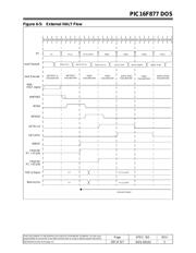
6.3 Background Debugger Control
This section describes the hardware re
q
uirements that
back
g
round debu
gg
in
g
imposes on the PIC16F877
desi
g
n as well as the functional description of the back-
g
round debu
gg
er s
y
stem.
6.3.1 Introduction
Traditionall
y
, embedded s
y
stem en
g
ineers use in circuit
emulators to debu
g
s
y
stem hardware and software. While
these emulators work well for man
y
embedded s
y
stems,
the
y
pose a number of problems that limit their effective-
ness:
•Hi
g
h cost of purchasin
g
emulators
(
$800.00 to
$3000+
)
per s
y
stem prevents man
y
customers from
bu
y
in
g
and usin
g
them
• Limited hi
g
h fre
q
uenc
y
support
(
10 Mhz limit on
PIC16CXX
)
• Limited volta
g
e ran
g
e
(
+5 Volt s
y
stem onl
y)
• Serious interconnect problems with surface mount
packa
g
es
• Inabilit
y
to dia
g
nose production board problems
• Inabilit
y
to easil
y
fine tune software for initial proto-
t
y
pe s
y
stems
Back
g
round debu
gg
er support solves these limitations of
in circuit emulators.
Back
g
round debu
gg
ers re
q
uire breakpoint address,
peripheral freeze, halt lo
g
ic and a non-maskable debu
g
-
g
er invocation address. A software or hardware commu-
nication protocol is established between the Tar
g
et
processor
(
which runs the back
g
round debu
gg
er
)
and the
debu
gg
er interface that connects to the PC runnin
g
MPLAB.
A software s
y
nchronous protocol can be implemented to
communicate between the 16F877 usin
g
the ICSP pins
(
RB6/RB7
)
and the PC runnin
g
MPLAB throu
g
h a debu
g
-
g
er interface module. This debu
gg
er interface module
can also perform In Circuit Serial Pro
g
rammin
g
for auto-
matic download of updated software. No additional com-
munication hardware is needed. However, a back
g
round
debu
gg
er cannot completel
y
be implemented in software
- it needs a small amount of hardware assistance with
interrupts, peripheral freezin
g
and breakpoints.
The desi
g
n, build and market the debu
gg
er/pro
g
rammer
interface module to MPLAB will be done throu
g
h a Bu
y
/
Re-sell a
g
reement with 3rd part
y
developers; much like
ICEPIC. There will also be a 3rd part
y
DLL development.
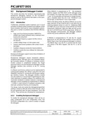
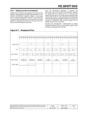
6.3.2 Enabling Background debugger
To enable the back
g
round debu
gg
er, there will be an
extra confi
g
uration bit in the confi
g
uration word. The
EEPROM confi
g
uration bit is used to enable or disable
the debu
gg
er.
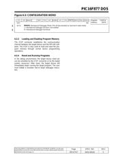
When BKBUG is pro
g
rammed to “0”, the breakpoint
address re
g
ister and RB6 HIGH->LOW debu
gg
er entr
y
are enabled. The sin
g
le step mode is also enabled. RB6/
7 user I/O functionalit
y
and interrupt on chan
g
e function-
alit
y
is disabled when this bit is set. TRISB<6:7> are
forced hi
g
h, so that RB<6:7> are in input mode.
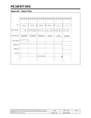
While in the debu
g
mode, the debu
g
software can access
either RB<5:0> of the PORTB pins or
j
ust RB<7:6> b
y
switchin
g
between banks 0:1 and 2:3. Addresses 006h
and 086h will access bits<5:0> of the PORTB and TRISB
respectivel
y
. Addresses 106h and 186h will onl
y
access
bits <6:7> of PORTB and TRISB respectivel
y
. While run-
nin
g
debu
gg
er communication, the debu
gg
er software
should onl
y
access addresses 106h and 186h.
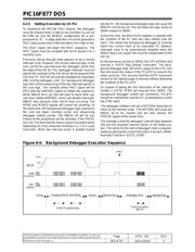
If BKBUG is pro
g
rammed to “0” and the PC e
q
uals
BKA<12:0>
(
or the RB6 Halt condition occurs
)
and the
INBUG fla
g
is clear, the back
g
round debu
gg
er is entered.
The INBUG fla
g
is set, the PC is pushed onto the stack
and stored in the BKA re
g
ister, and the PC is set to
1F00h.
器件 Datasheet 文档搜索
AiEMA 数据库涵盖高达 72,405,303 个元件的数据手册,每天更新 5,000 多个 PDF 文件
