Datasheet 搜索 > 微控制器 > Microchip(微芯) > PIC18F6527-I/PT 数据手册 > PIC18F6527-I/PT 其他数据使用手册 1/10 页
 器件3D模型
¥ 56.691
PIC18F6527-I/PT 其他数据使用手册 - Microchip(微芯)
制造商:
Microchip(微芯)
分类:
微控制器
封装:
TQFP-64
描述:
PIC18F6527/6622/6627/6722 8 位闪存微控制器### PIC18 微控制器
Pictures:
3D模型
符号图
焊盘图
引脚图
产品图
PIC18F6527-I/PT数据手册
Page:
of 10 Go
若手册格式错乱,请下载阅览PDF原文件
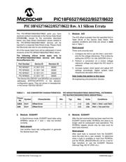
© 2006 Microchip Technology Inc. DS80253B-page 1
PIC18F6527/6622/8527/8622
The PIC18F6527/6622/8527/8622 parts you have
received conform functionally to the Device Data Sheet
(DS39646B), except for the anomalies described
below. Any Data Sheet Clarification issues related to
the PIC18F6527/6622/8527/8622 devices will be
reported in a separate Data Sheet errata. Please check
the Microchip web site for any existing issues.
All of the issues listed here will be addressed in future
revisions of the PIC18F6527/6622/8527/8622 silicon.
The following silicon errata apply only to
PIC18F6527/6622/8527/8622 devices with these
Device/Revision IDs:
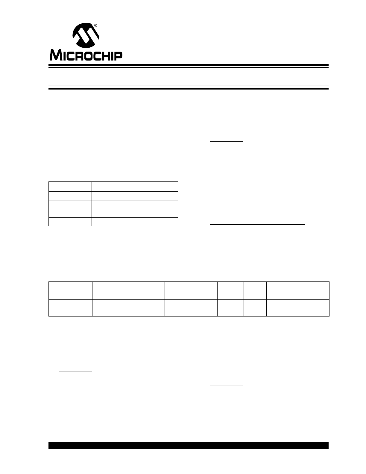
1. Module: A/D
The A/D offset is greater than the specified limit in
Table 28-26 of the Device Data Sheet. The
updated conditions and limits are shown in bold
text in Table 1.
Work around
Three work arounds exist.
1. Configure the A/D to use the V
REF+ and VREF-
pins for the voltage references. This is done by
setting the VCFG<1:0> bits (ADCON1<5:4>).
2. Perform a conversion on a known voltage
reference voltage and adjust the A/D result in
software.
3. Increase system clock speed and adjust A/D
settings accordingly. Higher system clock
frequencies decrease offset error.
Date Codes that pertain to this issue:
All engineering and production devices.
TABLE 1: A/D CONVERTER CHARACTERISTICS: PIC18F6X27/6X22/8X27/8X22 (INDUSTRIAL, EXTENDED)
PIC18LF6X27/6X22/8X27/8X22 (INDUSTRIAL)
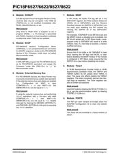
2. Module: EUSART
In Synchronous mode, EUSART baud rates using
SPBRGx values of ‘0’ and ‘1’ may not function
correctly.
Work around
Use another baud rate configuration to generate
the desired baud rate.
3. Module: EUSART
After the last received byte has been read from the
EUSART receive buffer, RCREGx, the value is no
longer valid for subsequent read operations. The
RCREGx register should only be read once for
each byte received.
Work around
After each byte is received from the EUSART,
store the byte into a user variable. To determine
when a byte is available to read from RCREGx,
poll the RCIDL (BAUDCONx<6>) bit for a low-to-
high transition or use the EUSART Receive
Interrupt Flag, RC1IF (PIR1<5>).
Part Number Device ID Revision ID
PIC18F6527 01 0011 010 00000
PIC18F6622 01 0011 100 00000
PIC18F8527 01 0011 011 00000
PIC18F8622 01 0011 101 00000
The Device IDs (DEVID1 and DEVID2) are located at
addresses 3FFFFEh:3FFFFFh in the device’s
configuration space. They are shown in hexadecimal
in the format “DEVID2 DEVID1”.
Param
No.
Symbol Characteristic Min Typ Max Units Conditions
A06A E
OFF Offset Error — — ±1.5 LSb VREF = VREF+ and VREF-
A06 EOFF Offset Error ——±3.5 LSb VREF = VSS and VDD
PIC18F6527/6622/8527/8622 Rev. A1 Silicon Errata
器件 Datasheet 文档搜索
AiEMA 数据库涵盖高达 72,405,303 个元件的数据手册,每天更新 5,000 多个 PDF 文件
