Datasheet 搜索 > 微控制器 > Microchip(微芯) > PIC18F8723T-I/PT 数据手册 > PIC18F8723T-I/PT 其他数据使用手册 1/6 页
 器件3D模型
¥ 42.339
PIC18F8723T-I/PT 其他数据使用手册 - Microchip(微芯)
制造商:
Microchip(微芯)
分类:
微控制器
封装:
TQFP-80
Pictures:
3D模型
符号图
焊盘图
引脚图
产品图
PIC18F8723T-I/PT数据手册
Page:
of 6 Go
若手册格式错乱,请下载阅览PDF原文件
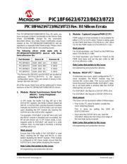
2010 Microchip Technology Inc. DS80342B-page 1
PIC18F6623/6723/8623/8723
The PIC18F6623/6723/8623/8723 Rev. B1 parts you
have received conform functionally to the Device Data
Sheet (DS39894B), except for the anomalies
described below. Any Data Sheet Clarification issues
related to the PIC18F6623/6723/8623/8723 will be
reported in a separate Data Sheet errata. Please check
the Microchip web site for any existing issues.
The following silicon errata apply only to
PIC18F6623/6723/8623/8723 devices with these
Device/Revision IDs:
All of the issues listed here will be addressed in future
revisions of the PIC18F6623/6723/8623/8723 silicon.
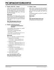
1. Module: Master Synchronous Serial Port
(MSSP) – Serial Peripheral
Interface (SPI)
In SPI mode, the Buffer Full flag (BF bit in the
SSPxSTAT register), the Write Collision Detect bit
(WCOL in SSPxCON1) and the Receive Overflow
Indicator bit (SSPOV in SSPxCON1) are not reset
upon disabling the SPI module (by clearing the
SSPEN bit in the SSPxCON1 register).
For example, if SSPxBUF is full (BF bit is set), and
the MSSP module is disabled and re-enabled, the
BF bit will remain set. In SPI Slave mode, a sub-
sequent write to SSPxBUF will result in a write
collision. Also, if a new byte is received, a receive
overflow will occur.
Work around
Ensure that if the buffer is full, SSPxBUF is read
(thus, clearing the BF flag) and WCOL is clear
before disabling the MSSP module. If the module
is configured in SPI Slave mode, ensure that the
SSPOV bit is clear before disabling the module.
Date Codes that pertain to this issue:
All engineering and production devices.
2. Module: Capture/Compare/PWM (CCP)
PWM output of 10-bit resolution is not available for
either CCP4 or CCP5 when Timer4 is being used
as the PWM time base (T3CON<6,3> = 01, 10 or
11) for the PWM mode (CCPxCON<3:2> = 11).
Work around
For 10-bit resolution, use Timer2 as the PWM time
base (T3CON<6,3> = 00).
For 8-bit resolution, use Timer4 or Timer2 as the
PWM time base and set the two LSBs to ‘00’
(CCPxCON<5:4> = 00).
Date Codes that pertain to this issue:
All engineering and production devices.
3. Module: MSSP (I
2
C™ Slave)
In extremely rare cases, when configured for I
2
C™
slave reception, the MSSP module may not
receive the correct data. This occurs only if the
Serial Receive/Transmit Buffer (SSPxBUF) regis-
ter is not read within a window after the SSPxIF
interrupt has occurred.
For SSP1BUF, the flag bit is SSP1IF (PIR1<3>).
For SSP2BUF, the flag bit is SSP2IF (PIR3<7>).
Work around
The issue can be resolved in either of these ways:
• Prior to the I
2
C slave reception, enable the
clock stretching feature.
This is done by setting the SEN bit
(SSP1CON2<0>).
• Each time the SSPxIF bit is set, read the
SSPxBUF before the first rising clock edge of
the next byte being received.
Date Codes that pertain to this issue:
All engineering and production devices.
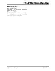
Part Number Device ID Revision ID
PIC18F6623 0100 1001 110 0 0010
PIC18F6723 0100 1010 000 0 0010
PIC18F8623 0100 1001 111 0 0010
PIC18F8723 0100 1010 001 0 0010
The Device IDs (DEVID1 and DEVID2) are located at
addresses 3FFFFEh:3FFFFFh in the device’s
configuration space. They are shown in binary in the
format “DEVID2 DEVID1”.
PIC18F6623/6723/8623/8723 Rev. B1 Silicon Errata
器件 Datasheet 文档搜索
AiEMA 数据库涵盖高达 72,405,303 个元件的数据手册,每天更新 5,000 多个 PDF 文件
