Datasheet 搜索 > 晶闸管 > Bourns J.W. Miller(伯恩斯) > TIC206MS 数据手册 > TIC206MS 其他数据使用手册 1/3 页


¥ 0
TIC206MS 其他数据使用手册 - Bourns J.W. Miller(伯恩斯)
制造商:
Bourns J.W. Miller(伯恩斯)
分类:
晶闸管
封装:
TO-220
Pictures:
3D模型
符号图
焊盘图
引脚图
产品图
页面导航:
技术参数、封装参数在P1P2P3
导航目录
TIC206MS数据手册
Page:
of 3 Go
若手册格式错乱,请下载阅览PDF原文件
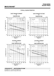
TIC206 SERIES
SILICON TRIACS
1
DECEMBER 1971 - REVISED SEPTEMBER 2002
Specifications are subject to change without notice.
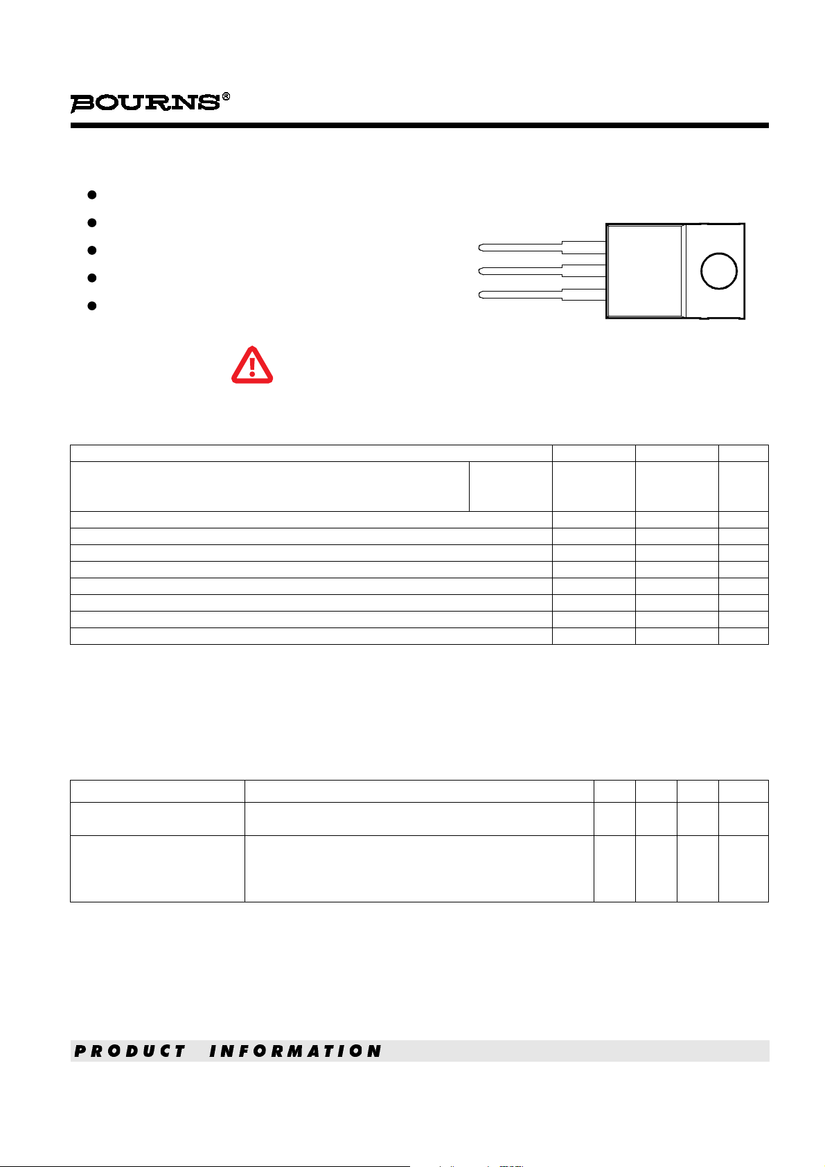
MT1
MT2
G
TO-220 PACKAGE
(TOP VIEW)
Pin 2 is in electrical contact with the mounting base.
MDC2ACA
1
2
3
Sensitive Gate Triacs
4 A RMS
Glass Passivated Wafer
400 V to 700 V Off-State Voltage
Max I
GT
of 5 mA (Quadrants 1 - 3)
absolute maximum ratings over operating case temperature (unless otherwise noted)
NOTES: 1. These values apply bidirectionally for any value of resistance between the gate and Main Terminal 1.
2. This value applies for 50-Hz full-sine-wave operation with resistive load. Above 85°C derate linearly to 110°C case temperature at
the rate of 160 mA/°C.
3. This value applies for one 50-Hz full-sine-wave when the device is operating at (or below) the rated value of on-state current. Surge
may be repeated aft
er the device has returned to original thermal equilibrium. During the surge, gate control may be lost.
4. This value applies for a maximum averaging time of 20 ms.
RATING SYMBOL VALUE UNIT
Repetitive peak off-state voltage (see Note 1)
TIC206D
TIC206M
TIC206S
V
DRM
400
600
700
V
Full-cycle RMS on-state current at (or below) 85°C case temperature (see Note 2) I
T(RMS)
4 A
Peak on-state surge current full-sine-wave at (or below) 25°C case temperature (see Note 3) I
TSM
25 A
Peak gate current I
GM
±0.2 A
Peak gate po
wer dissipation at (or below) 85°C case temperature (pulse width ≤ 200 μs) P
GM
1.3 W
Average gate power dissipation at (or below) 85°C case temperature (see Note 4) P
G(AV)
0.3 W
Operating case temperature range T
C
-40 to +110 °C
Storage temperature range T
stg
-40 to +125 °C
Lead temperature 1.6 mm from case for 10 seconds T
L
230 °C
electrical characteristics at 25°C case temperature (unless otherwise noted )
PARAMETER TEST CONDITIONS MIN TYP MAX UNIT
I
DRM
Repetitive peak
off-state current
V
D
= rated V
DRM
I
G
= 0 T
C
= 110°C ±1 mA
I
GT
Gate trigger
current
V
supply
= +12 V†
V
supply
= +12 V†
V
supply
= -12 V†
V
supply
= -12 V†
R
L
= 10 Ω
R
L
= 10 Ω
R
L
= 10 Ω
R
L
= 10 Ω
t
p(g)
> 20 μs
t
p(g)
> 20 μs
t
p(g)
> 20 μs
t
p(g)
> 20 μs
0.9
-2.2
-1.8
2.4
5
-5
-5
10
mA
† All voltages are with respect to Main Terminal 1.
This series is currently available,
but not recommended for new
designs.
器件 Datasheet 文档搜索
AiEMA 数据库涵盖高达 72,405,303 个元件的数据手册,每天更新 5,000 多个 PDF 文件
