Datasheet 搜索 > 双极性晶体管 > Multicomp > TIP42C 数据手册 > TIP42C 其他数据使用手册 1/6 页

¥ 1.655
TIP42C 其他数据使用手册 - Multicomp
制造商:
Multicomp
分类:
双极性晶体管
封装:
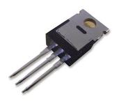
TO-220
描述:
MULTICOMP TIP42C 单晶体管 双极, 通用, PNP, -100 V, 3 MHz, 65 W, -6 A, 15 hFE
Pictures:
3D模型
符号图
焊盘图
引脚图
产品图
页面导航:
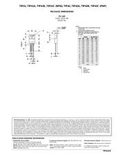
封装尺寸在P6
型号编码规则在P1P2P6
标记信息在P1
电气规格在P2
导航目录
TIP42C数据手册
Page:
of 6 Go
若手册格式错乱,请下载阅览PDF原文件
© Semiconductor Components Industries, LLC, 2005
September, 2005 − Rev. 6
1 Publication Order Number:
TIP41A/D
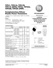
TIP41, TIP41A, TIP41B,
TIP41C (NPN); TIP42, TIP42A,
TIP42B, TIP42C (PNP)
Complementary Silicon
Plastic Power Transistors
Designed for use in general purpose amplifier and switching
applications.
Features
• ESD Ratings: Machine Model, C; > 400 V
Human Body Model, 3B; > 8000 V
• Epoxy Meets UL 94 V−0 @ 0.125 in
• Pb−Free Packages are Available*
MAXIMUM RATINGS
Rating Symbol Value Unit
Collector−Emitter Voltage TIP41, TIP42
TIP41A, TIP42A
TIP41B, TIP42B
TIP41C, TIP42C
V
CEO
40
60
80
100
Vdc
Collector−Base Voltage TIP41, TIP42
TIP41A, TIP42A
TIP41B, TIP42B
TIP41C, TIP42C
V
CB
40
60
80
100
Vdc
Emitter−Base Voltage V
EB
5.0 Vdc
Collector Current− Continuous
Peak
I
C
6.0
10
Adc
Base Current I
B
2.0 Adc
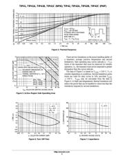
Total Power Dissipation @ T
C
= 25°C
Derate above 25°C
P
D
65
0.52
W
W/°C
Total Power Dissipation @ T
A
= 25°C
Derate above 25°C
P
D
2.0
0.016
W
W/°C
Unclamped Inductive Load Energy
(Note 1)
E 62.5 mJ
Operating and Storage Junction,
Temperature Range
T
J
, T
stg
–65 to
+150
°C
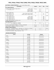
THERMAL CHARACTERISTICS
Characteristic Symbol Max Unit
Thermal Resistance, Junction−to−Case
R
q
JC
1.67 °C/W
Thermal Resistance, Junction−to−Ambient
R
q
JA
57 °C/W
Maximum ratings are those values beyond which device damage can occur.
Maximum ratings applied to the device are individual stress limit values (not
normal operating conditions) and are not valid simultaneously. If these limits are
exceeded, device functional operation is not implied, damage may occur and
reliability may be affected.
1. I
C
= 2.5 A, L = 20 mH, P.R.F. = 10 Hz, V
CC
= 10 V, R
BE
= 100 W.
*For additional information on our Pb−Free strategy and soldering details, please
download the ON Semiconductor Soldering and Mounting Techniques
Reference Manual, SOLDERRM/D.
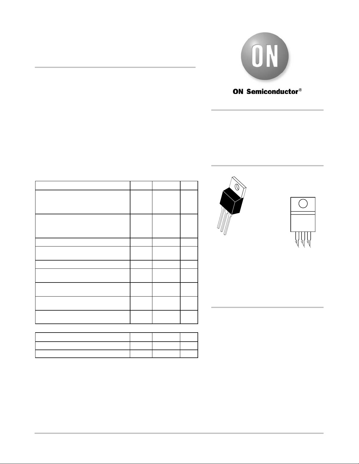
TO−220AB
CASE 221A
STYLE 1
MARKING
DIAGRAM
6 AMPERE
COMPLEMENTARY SILICON
POWER TRANSISTORS
40−60−80−100 VOLTS,
65 WATTS
http://onsemi.com
1
2
3
4
TIP4xx = Device Code
xx = 1, 1A, 1B, 1C
2, 2A, 2B, 2C
A = Assembly Location
Y = Year
WW = Work Week
G = Pb−Free Package
TIP4xxG
AYWW
See detailed ordering and shipping information in the package
dimensions section on page 2 of this data sheet.
ORDERING INFORMATION
器件 Datasheet 文档搜索
AiEMA 数据库涵盖高达 72,405,303 个元件的数据手册,每天更新 5,000 多个 PDF 文件
