Datasheet 搜索 > UART接口芯片 > TI(德州仪器) > TL16C550CPFB 数据手册 > TL16C550CPFB 其他数据使用手册 1/43 页
 器件3D模型
¥ 8.85
TL16C550CPFB 其他数据使用手册 - TI(德州仪器)
制造商:
TI(德州仪器)
分类:
UART接口芯片
封装:
TQFP-48
描述:
TEXAS INSTRUMENTS TL16C550CPFB. 芯片, 收发器, 最小电源电压3.3V
Pictures:
3D模型
符号图
焊盘图
引脚图
产品图
页面导航:
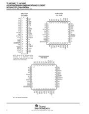
封装尺寸在P35P37P38
封装信息在P35P36P37P38
应用领域在P43
导航目录
TL16C550CPFB数据手册
Page:
of 43 Go
若手册格式错乱,请下载阅览PDF原文件

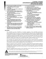
SLLS177H − MARCH 1994 − REVISED JANUARY 2006
1
POST OFFICE BOX 655303 • DALLAS, TEXAS 75265
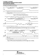
D Programmable Auto-RTS and Auto-CTS
D In Auto-CTS Mode, CTS Controls
Transmitter
D In Auto-RTS Mode, RCV FIFO Contents and
Threshold Control RTS
D Serial and Modem Control Outputs Drive a
RJ11 Cable Directly When Equipment Is on
the Same Power Drop
D Capable of Running With All Existing
TL16C450 Software
D After Reset, All Registers Are Identical to
the TL16C450 Register Set
D Up to 16-MHz Clock Rate for up to 1-Mbaud
Operation
D In the TL16C450 Mode, Hold and Shift
Registers Eliminate the Need for Precise
Synchronization Between the CPU and
Serial Data
D Programmable Baud Rate Generator Allows
Division of Any Input Reference Clock by 1
to (2
16
−1) and Generates an Internal 16×
Clock
D Standard Asynchronous Communication
Bits (Start, Stop, and Parity) Added to or
Deleted From the Serial Data Stream
D 5-V and 3.3-V Operation
D Independent Receiver Clock Input
D Transmit, Receive, Line Status, and Data
Set Interrupts Independently Controlled
D Fully Programmable Serial Interface
Characteristics:
− 5-, 6-, 7-, or 8-Bit Characters
− Even-, Odd-, or No-Parity Bit Generation
and Detection
− 1-, 1 1/2-, or 2-Stop Bit Generation
− Baud Generation (dc to 1 Mbit/s)
D False-Start Bit Detection
D Complete Status Reporting Capabilities
D 3-State Output TTL Drive Capabilities for
Bidirectional Data Bus and Control Bus
D Line Break Generation and Detection
D Internal Diagnostic Capabilities:
− Loopback Controls for Communications
Link Fault Isolation
− Break, Parity, Overrun, and Framing
Error Simulation
D Fully Prioritized Interrupt System Controls
D Modem Control Functions (CTS, RTS, DSR,
DTR
, RI, and DCD)
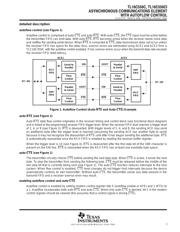
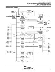
description
The TL16C550C and the TL16C550CI are functional upgrades of the TL16C550B asynchronous
communications element (ACE), which in turn is a functional upgrade of the TL16C450. Functionally equivalent
to the TL16C450 on power up (character or TL16C450 mode), the TL16C550C and the TL16C550CI, like the
TL16C550B, can be placed in an alternate FIFO mode. This relieves the CPU of excessive software overhead
by buffering received and transmitted characters. The receiver and transmitter FIFOs store up to 16 bytes
including three additional bits of error status per byte for the receiver FIFO. In the FIFO mode, there is a
selectable autoflow control feature that can significantly reduce software overload and increase system
efficiency by automatically controlling serial data flow using RTS
output and CTS input signals.
The TL16C550C and TL16C550CI perform serial-to-parallel conversions on data received from a peripheral
device or modem and parallel-to-serial conversion on data received from its CPU. The CPU can read the ACE
status at any time. The ACE includes complete modem control capability and a processor interrupt system that
can be tailored to minimize software management of the communications link.
Both the TL16C550C and the TL16C550CI ACE include a programmable baud rate generator capable of
dividing a reference clock by divisors from 1 to 65535 and producing a 16× reference clock for the internal
transmitter logic. Provisions are included to use this 16× clock for the receiver logic. The ACE accommodates
a 1-Mbaud serial rate (16-MHz input clock) so that a bit time is 1 µs and a typical character time is 10 µs (start
bit, 8 data bits, stop bit).
Two of the TL16C450 terminal functions on the TL16C550C and the TL16C550CI have been changed to
TXRDY
and RXRDY, which provide signaling to a DMA controller.
Please be aware that an important notice concerning availability, standard warranty, and use in critical applications of
Texas Instruments semiconductor products and disclaimers thereto appears at the end of this data sheet.
! " #$%! " &$'(#! )!%*
)$#!" # ! "&%##!" &% !+% !%" %," "!$%!"
"!)) -!.* )$#! &#%""/ )%" ! %#%""(. #($)%
!%"!/ (( &%!%"*
Copyright 1994 − 2006, Texas Instruments Incorporated
器件 Datasheet 文档搜索
AiEMA 数据库涵盖高达 72,405,303 个元件的数据手册,每天更新 5,000 多个 PDF 文件
