Datasheet 搜索 > TI(德州仪器) > TPD1E10B06-Q1EVM 数据手册 > TPD1E10B06-Q1EVM 其他数据使用手册 1/14 页

¥ 411.618
TPD1E10B06-Q1EVM 其他数据使用手册 - TI(德州仪器)
制造商:
TI(德州仪器)
Pictures:
3D模型
符号图
焊盘图
引脚图
产品图
页面导航:

导航目录
TPD1E10B06-Q1EVM数据手册
Page:
of 14 Go
若手册格式错乱,请下载阅览PDF原文件
WARP2 SERIES IGBT WITH
ULTRAFAST SOFT RECOVERY DIODE
AUIRGP35B60PD-E
01/11/10
Features
• NPT Technology, Positive Temperature Coefficient
• Lower V
CE
(SAT)
• Lower Parasitic Capacitances
• Minimal Tail Current
• HEXFRED Ultra Fast Soft-Recovery Co-Pack Diode
• Tighter Distribution of Parameters
• Higher Reliability
• Lead-Free, RoHS Compliant
• Automotive Qualified*
Benefits
• Parallel Operation for Higher Current Applications
• Lower Conduction Losses and Switching Losses
• Higher Switching Frequency up to 150KHz
Applications
• PFC and ZVS SMPS Circuits
• DC/DC Converter Charger
1 www.irf.com
PD - 97619
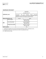
AUTOMOTIVE GRADE
GC E
Gate Collector Emitter
TO-247AD
AUIRGP35B60PD-E
G
C
E
C
E
G
n-channel
C
V
CES
= 600V
V
CE(on)
typ. = 1.85V
@ V
GE
= 15V
I
C
= 22A
Equivalent MOSFET
Parameters
R
CE(on)
typ. = 84mΩ
I
D
(FET equivalent) = 35A
*Qualification standards can be found at http://www.irf.com/
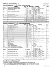
Absolute Maximum Ratings
Stresses beyond those listed under “Absolute Maximum Ratings” may cause permanent damage to the device. These are stress ratings only; and
functional operation of the device at these or any other condition beyond those indicated in the specifications is not implied. Exposure to absolute-
maximum-rated conditions for extended periods may affect device reliability. The thermal resistance and power dissipation ratings are measured
under board mounted and still air conditions. Ambient temperature (T
A
) is 25°C, unless otherwise specified.
Parameter Max. Units
V
CES
Collector-to-Emitter Voltage 600 V
I
C
@ T
C
= 25°C Continuous Collector Current 60
I
C
@ T
C
= 100°C Continuous Collector Current 34
I
CM
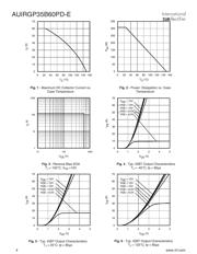
Pulse Collector Current (Ref. Fig. C.T.4) 120
I
LM
Clamped Inductive Load Current
d
120 A
I
F
@ T
C
= 25°C Diode Continous Forward Current 40
I
F
@ T
C
= 100°C Diode Continous Forward Current 15
I
FRM
Maximum Repetitive Forward Current
e
60
V
GE
Gate-to-Emitter Voltage ±20 V
P
D
@ T
C
= 25°C Maximum Power Dissipation 308 W
P
D
@ T
C
= 100°C Maximum Power Dissipation 123
T
J
Operating Junction and -55 to +150
T
STG
Storage Temperature Range °C
Soldering Temperature for 10 sec. 300 (0.063 in. (1.6mm) from case)
Mounting Torque, 6-32 or M3 Screw 10 lbf·in (1.1 N·m)
Thermal Resistance
Parameter Min. Typ. Max. Units
R
θJC
(IGBT)
Thermal Resistance Junction-to-Case-(each IGBT) ––– ––– 0.41 °C/W
R
θJC
(Diode)
Thermal Resistance Junction-to-Case-(each Diode) ––– ––– 1.7
R
θCS
Thermal Resistance, Case-to-Sink (flat, greased surface) ––– 0.50 –––
R
θJA
Thermal Resistance, Junction-to-Ambient (typical socket mount) ––– ––– 40
Weight ––– 6.0 (0.21) ––– g (oz)
器件 Datasheet 文档搜索
AiEMA 数据库涵盖高达 72,405,303 个元件的数据手册,每天更新 5,000 多个 PDF 文件
