Datasheet 搜索 > 铝电解电容 > Nichicon(尼吉康) > UPM1V101MPD1TA 数据手册 > UPM1V101MPD1TA 其他数据使用手册 1/10 页

¥ 1.103
UPM1V101MPD1TA 其他数据使用手册 - Nichicon(尼吉康)
制造商:
Nichicon(尼吉康)
分类:
铝电解电容
封装:
Radial, CAN
描述:
插件电容
Pictures:
3D模型
符号图
焊盘图
引脚图
产品图
页面导航:
标记信息在P1P10
技术参数、封装参数在P1P10
电气规格在P1P10
导航目录
UPM1V101MPD1TA数据手册
Page:
of 10 Go
若手册格式错乱,请下载阅览PDF原文件
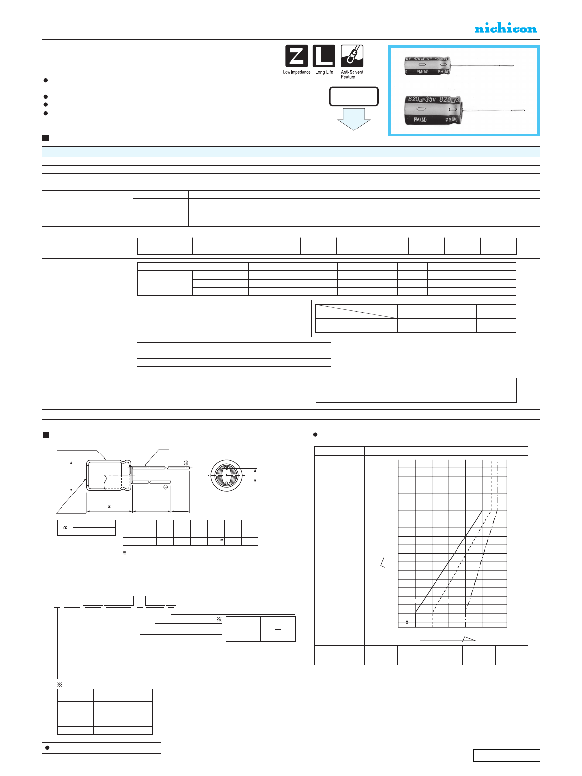
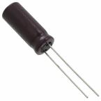
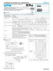
ALUMINUM ELECTROLYTIC CAPACITORS
P.27
CAT.8100J
Please refer to page 18, 19 about the formed or taped product spec.
Please refer to page 4 for the minimum order quantity.
UEP
φ
δ
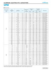
2
P
2
.7 . . 2 P7
. . P
22 . . 2. P22
8. . . 72 PP
7 8. . . 8 P7P
. PP
22 2.2 . 2 2 P22
2.2 . . P
7 2.2 . . P7
. . 8 P2
. 2 P
2.2 . . 8 P22
. . . 22 P
.7 . 7. 22 P7
. . 7 P
22 8. . P22P
8. . . 77 PP
7 2. . 7. P7P
2 . PP
22 2.2 . P22
2 . P
7 . . 7 P7
. .2 .27 2 P
.7 . .2 8.88 P7
. .2 8. P
22 8. .2 .8 8 P22P
2. .2 2.7 8 PP
7 .2 88.8 P7P
2.2 .2 8 22 P
22 2 .2 .8 P22
. .2 2.7 P
7 8. .2 888. 8 P7
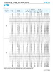
2
. P2
2.2 . . . 2 P222
. . . . 2 P2
.7 . . . P27
8. . P2P
22 . 7 P222P
2.2 . P2
7 2.2 . 7 P27
2 . P2
22 8. . P222
■
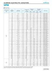
Dimensions
For cut leads, formed leads or taped parts, please add the appropriate code after the size code (12th digit ).
If there is no size code in the part number, please add size code “1” and then add the appropriate code.
ALUMINUM ELECTROLYTIC CAPACITORS
P.277
CAT.8100J
U
1
P
2
M
3
1
4
E
5
4
6
7
7
1
8
M
9
P
10
D
11
12
Configuration
Size code
Capacitance tolerance ( ±20%)
Rated capacitance (470
µF)
Rated voltage (25V)
Series name
Type
Type
Small Dia
Low Profile
Code
6
φ D
5
Pb-free leadwire
Pb-free PET sleeve
DD
6.3 ED
8 · 10 PD
12.5 to 18 HD
Configuration
(φ6.3up)
15
MIN
4
MIN
Sleeve (P.E.T.)
Pressure
relief vent
φ
d
φD
+
0.5
MAX.
L
+ MAX.
P
±0.5
(φD < 10) 1.5
(φD
>
=
10) 2.0
φD
P
φd
5
2.0
0.5
6.3
2.5
0.5
8
3.5
0.6
10
5.0 5.0
0.6
12.5
0.6
16
7.5
0.8
18
7.5
0.8
(mm)
In case L > 25 for the φ12.5 dia. unit, lead dia. φ d = 0.8mm.
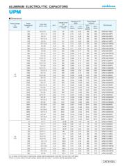
15000
10000
6800
4700
3300
2200
1500
1000
680
470
330
220
150
100
68
47
33
22
15
10
2.2
00.5 0.60.7 0.80.9 1.0
Frequency coefficient
Cap.(μF)
300Hz 1kHz120Hz
Frequency coefficientRated voltage
6.3 to 100V
(10kHz to
200kHz=1)
160 to 450V
50Hz 120Hz 300Hz 1kHz
10kHz or more
0.80 1.00 1.25 1.40 1.60
Low Impedance, High Reliability
UPM
(Through 100V only)
UPM
UPW
Smaller
High reliability withstanding 5000 hour load life at +105
°C
(3000/2000 hours for
smaller case sizes as specified below).
Capacitance ranges available based on the numerical values in E12 series under JIS.
Compliant to the RoHS directive (2011/65/EU,(EU)2015/863).
AEC-Q200 compliant. Please contact us for details.
Specifications
Dimension table in next page.
Radial Lead Type
Type numbering system (Example : 25V 470
µ
F)
• Please refer to page 18 about the end seal configuration.
Frequency coefficient of rated ripple current
Item
Marking
Shelf Life
Category Temperature Range
Rated Voltage Range
Rated Capacitance Range
Capacitance Tolerance
Leakage Current
Tangent of loss angle (tan δ)
Stability at Low Temperature
Endurance
Performance Characteristics
– 55 to +105°C (6.3 to 100V), –40 to +105°C (160 to 400V), –25 to +105°C (450V)
6.3 to 450V
1 to 15000µF
± 20% at 120Hz, 20°C
Rated Voltage (V)
Leakage current
For capacitance of more than 1000µF, add 0.02 for every increase of 1000µF. Measurement frequency : 120Hz at 20°C
120Hz
After 1 minute's application of rated voltage at 20°C, leakage current is
not more than 0.03CV or 4 (µA), whichever is greater.
Printed with white color letter on dark brown sleeve.
The specifications listed below shall be met when the capacitors
are restored to 20°C after D.C. bias plus rated ripple current is
applied at 105°C for the condition listed at right.The peak voltage
shall not exceed the rated voltage.
160 to 450
After 1 minute's application of rated voltage at 20°C,
CV
<
=
1000 :
I
= 0.1CV+40 (µA) or less.
CV > 1000 :
I
= 0.04CV+100 (µA) or less.
Rated voltage (V)
Impedance
ratio (MAX.)
Z–25°C / Z+20°C
Z–40°C / Z+20°C
Z–55°C / Z+20°C
Rated Voltage (V)
tan δ (MAX.)
6.3
0.22
6.3 · 10
—
—
4
16
—
—
3
25 · 35
—
—
3
50 to 100
—
—
2
160
·
200
—
4
—
250
—
6
—
315
·
350
—
8
—
400
—
10
—
450
15
—
—
10
0.19
16
0.16
25
0.14
35
0.12
50
0.10
63 to 100
0.08
160 to 350
0.20
400 · 450
0.25
6.3 to 100
Leakage current
tan δ
Capacitance change
Less than or equal to the initial specified value
200% or less than the initial specified value
Within ±20% of the initial capacitance value
Rated Voltage
φD(mm)
φ 5, φ
6.3
φ
8
>
=
φ10
6.3
〜
450V 2000h 3000h 5000h
h = hours
After storing the capacitors under no load at 105°C
for 1000 hours and then performing voltage treatment based
on JIS C 5101-4 clause 4.1 at 20°C, they shall meet the
characteristic requirements listed at right.
Leakage current
tan δ
Capacitance change
Less than or equal to the initial specified value
150% or less than the initial specified value
Within ±20% of the initial capacitance value
器件 Datasheet 文档搜索
AiEMA 数据库涵盖高达 72,405,303 个元件的数据手册,每天更新 5,000 多个 PDF 文件
