Datasheet 搜索 > 数模转换器 > ADI(亚德诺) > AD2S1210SST-EP-RL7 数据手册 > AD2S1210SST-EP-RL7 产品设计参考手册 1/16 页
 器件3D模型
¥ 23.496
AD2S1210SST-EP-RL7 产品设计参考手册 - ADI(亚德诺)
制造商:
ADI(亚德诺)
分类:
数模转换器
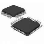
封装:
LQFP-48
Pictures:
3D模型
符号图
焊盘图
引脚图
产品图
页面导航:

导航目录
AD2S1210SST-EP-RL7数据手册
Page:
of 16 Go
若手册格式错乱,请下载阅览PDF原文件
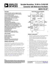
Variable Resolution, 10-Bit to 16-Bit R/D
Converter with Reference Oscillator
AD2S1210-EP
Rev. 0
Information furnished by Analog Devices is believed to be accurate and reliable. However, no
responsibility is assumed by Analog Devices for its use, nor for any infringements of patents or other
rights of third parties that may result from its use. Specifications subject to change without notice. No
license is granted by implication or otherwise under any patent or patent rights of Analog Devices.
Trademarks and registered trademarks are the property of their respective owners.
One Technology Way, P.O. Box 9106, Norwood, MA 02062-9106, U.S.A.
Tel: 781.329.4700
www.analog.com
Fax: 781.461.3113 ©2010 Analog Devices, Inc. All rights reserved.
FEATURES
Complete monolithic resolver-to-digital converter
3125 rps maximum tracking rate (10-bit resolution)
±2.5 arc minutes of accuracy
10-/12-/14-/16-bit resolution, set by user
Parallel and serial 10-bit to 16-bit data ports
Absolute position and velocity outputs
System fault detection
Programmable fault detection thresholds
Differential inputs
Incremental encoder emulation
Programmable sinusoidal oscillator on board
Compatible with DSP and SPI interface standards
5 V supply with 2.3 V to 5 V logic interface
Support defense and aerospace applications (AQEC)
Military temperature range (−55°C to +125°C)
Controlled manufacturing baseline
One assembly/test site
One fabrication site
Enhanced product change notification
Qualification data available upon request
APPLICATIONS
DC and ac servo motor control
Encoder emulation
Electric power steering
Electric vehicles
Integrated starter generators/alternators
Automotive motion sensing and control
GENERAL DESCRIPTION
The AD2S1210-EP is a complete 10-bit to 16-bit resolution
tracking resolver-to-digital converter, integrating an on-board
programmable sinusoidal oscillator that provides sine wave
excitation for resolvers.
The converter accepts 3.15 V p-p ± 27% input signals, in the range
of 2 kHz to 20 kHz on the sine and cosine inputs. A Type II
servo loop is employed to track the inputs and convert the input
sine and cosine information into a digital representation of the
input angle and velocity. The maximum tracking rate is 3125 rps.
Full details about this enhanced product, including theory of
operation, registers details, and applications information, are
available in the AD2S1210 data sheet, which should be
concluded in conjunction with this data sheet.
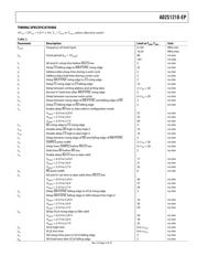
FUNCTIONAL BLOCK DIAGRAM
REFERENCE
OSCILLATOR
(DAC)
EXCI
TATION
OUTPUTS
AD2S1210-EP
ENCODER
EMULATION
SYNTHETIC
REFERENCE
RESET
DATA I/O
INPUTS
FROM
RESOLVER
ENCODER
EMULATION
OUTPUTS
VOLTAGE
REFERENCE
REFERENCE
PINS
INTERNAL
CLOCK
GENERATOR
CRYSTAL
TYPE II
TRACKING LOOP
FAULT
DETECTION
FAULT
DETECTION
OUTPUTS
POSITION
REGISTER
ADC
ADC
CONFIGURATION
REGISTER
MULTIPLEXER
DATA BUS OUTPUT
DATA I/O
VELOCITY
REGISTER
09154-001
Figure 1.
PRODUCT HIGHLIGHTS
1. Ratiometric tracking conversion. The Type II tracking loop
provides continuous output position data without
conversion delay. It also provides noise immunity and
tolerance of harmonic distortion on the reference and
input signals.
2. System fault detection. A fault detection circuit can sense
loss of resolver signals, out-of-range input signals, input
signal mismatch, or loss of position tracking. The fault
detection threshold levels can be individually programmed
by the user for optimization within a particular application.
3. Input signal range. The sine and cosine inputs can accept
differential input voltages of 3.15 V p-p ± 27%.
4. Programmable excitation frequency. Excitation frequency
is easily programmable to a number of standard frequencies
between 2 kHz and 20 kHz.
5. Triple format position data. Absolute 10-bit to 16-bit angular
position data is accessed via either a 16-bit parallel port or a
4-wire serial interface. Incremental encoder emulation is in
standard A-quad-B format with direction output available.
6. Digital velocity output. 10-bit to 16-bit signed digital
velocity accessed via either a 16-bit parallel port or a 4-wire
serial interface.
器件 Datasheet 文档搜索
AiEMA 数据库涵盖高达 72,405,303 个元件的数据手册,每天更新 5,000 多个 PDF 文件
