Datasheet 搜索 > 开发套件 > TI(德州仪器) > ADS1232REF 数据手册 > ADS1232REF 产品设计参考手册 6/31 页

¥ 1934.402
ADS1232REF 产品设计参考手册 - TI(德州仪器)
制造商:
TI(德州仪器)
分类:
开发套件
描述:
用户指南 USER GUIDE
Pictures:
3D模型
符号图
焊盘图
引脚图
产品图
页面导航:
原理图在P20P23P24P25P26P27P28
应用领域在P1P30
导航目录
ADS1232REF数据手册
Page:
of 31 Go
若手册格式错乱,请下载阅览PDF原文件

Getting Started
www.ti.com
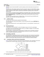
1.5 Connecting Other Sources
In general, the ADS1232REF can accurately measure any voltage in the input range of the ADS1232
ADC, as long as the following rules are observed:
• Never apply a negative voltage to the inputs of the ADS1232REF. The ADS1232 cannot accept
negative voltages at its input. Applying negative voltages may damage both the device and the
ADS1232REF. (The negative signs used in some signal names indicate inversion, not polarity.)
• Two channels are available. Be sure that the switch is set to the correct channel.
• For single-ended signals, ground the negative input or connect it to 2.5V. 2.5V is available from a
voltage divider by shorting J7; see Section 6.4.5 for details.
• The input range of the amplifier on the ADS1232 does not extend to the supplies. See the ADS1232
data sheet for details.
Note that Scale mode is designed only for use with load cells. Although it can be tested with a voltage
source or resistive divider, Scale mode does not, in general, display meaningful data unless a load cell is
connected and calibration is performed.
1.6 Connecting an External Clock
To connect an external clock, connect a clock oscillator to the EXTCLK test point. No settings need to be
changed; the ADS1232 will automatically use the attached clock.
The clock source must conform to 3.3V TTL or CMOS logic rules.
1.7 Common Tasks
1.7.1 Shorted-Input Noise Test
The noise measurements given in the product data sheet are taken with the inputs shorted to 2.5V. These
noise measurements can be replicated on the ADS1232REF with no external hardware. To set up these
measurements on the ADS1232REF, perform the following steps:
1. Move the mode switch to Analysis mode.
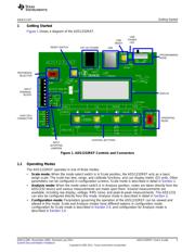
2. Short jumpers J8 and J7. (These jumpers are located very near the terminal block, and are marked
Input Shorting Jumpers in Figure 1.)
3. Set up the ADS1232 as desired, as described in the previous sections.
4. Hold down the DISP button. The display shows the current display mode. While holding down DISP,
press the UNIT button until the word on the left side is RMS.
5. While still holding down DISP, press the MODE button until the word on the right side is VOLT.
6. Release the DISP button. The display shows the word GOT followed by an increasing number. Once
the appropriate number of points is collected, the calculated noise voltage is displayed. This value is
the shorted-input RMS noise voltage, input-referred.
The first RMS noise measurement may be incorrect as a result of device settling. The second
measurement is generally correct.
For a detailed description of Analysis mode, see Section 3.
1.7.2 Measuring Mass
The following items are required to measure mass with the ADS1232REF:
• A load cell, connected as described in Section 1.4
• An object of known mass within the load cell range
To avoid performing calibration on each power-up, you can save the calibration settings to flash memory.
See Section 3.4.1 for details.
6
ADS1232REF User's Guide SBAU120B–November 2005–Revised July 2011
Submit Documentation Feedback
Copyright © 2005–2011, Texas Instruments Incorporated
器件 Datasheet 文档搜索
AiEMA 数据库涵盖高达 72,405,303 个元件的数据手册,每天更新 5,000 多个 PDF 文件
