Datasheet 搜索 > 开发板 > Silicon Labs(芯科) > C8051F320DK-U 数据手册 > C8051F320DK-U 产品设计参考手册 1/12 页

¥ 0
C8051F320DK-U 产品设计参考手册 - Silicon Labs(芯科)
制造商:
Silicon Labs(芯科)
分类:
开发板
Pictures:
3D模型
符号图
焊盘图
引脚图
产品图
页面导航:
引脚图在P8P9Hot
典型应用电路图在P12
原理图在P10
应用领域在P9
导航目录
C8051F320DK-U数据手册
Page:
of 12 Go
若手册格式错乱,请下载阅览PDF原文件
Rev. 0.9 2/14 Copyright © 2014 by Silicon Laboratories C8051F32x
C8051F32x
C8051F32X DEVELOPMENT KIT USER’S GUIDE
1. Kit Contents
The C8051F32x Development Kit contains the following items:
• C8051F320 Target Board
• C8051Fxxx Development Kit Quick-Start Guide
• AC to DC Power Adapter
• USB Debug Adapter (USB to Debug Interface)
• USB Cable
• CD-ROM
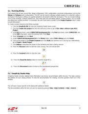
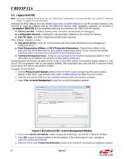
2. Hardware Setup Using a USB Debug Adapter
The target board is connected to a PC running the Silicon Laboratories IDE via the USB Debug Adapter as shown
in Figure 1.
1. Connect the USB Debug Adapter to the
DEBUG
connector on the target board with the 10-pin ribbon cable.
2. Connect one end of the USB cable to the USB connector on the USB Debug Adapter.
3. Connect the other end of the USB cable to a USB Port on the PC.
4. Connect the ac/dc power adapter to power jack P1 on the target board.
Notes:
• Use the Reset button in the IDE to reset the target when connected using a USB Debug Adapter.
• Remove power from the target board and the USB Debug Adapter before connecting or disconnecting the
ribbon cable from the target board. Connecting or disconnecting the cable when the devices have power can
damage the device and/or the USB Debug Adapter.
Figure 1. Hardware Setup Using a USB Debug Adapter
Note: The C8051F320 target board has the ability to be powered through the USB cable. To enable the USB-powered mode,
move the shorting block located at header J2 to header J11.
PC
USB
Cable
USB Debug Adapter
AC/DC
Adapter
Target Board
SILICON LABORATORIES
PWR
P1.6
P3.7RESET
Port 4Port 3Port 1
Port 2 Port 0
MCU
Silicon Laboratories
USB DEBUG ADAPTER
Run
StopPower
器件 Datasheet 文档搜索
AiEMA 数据库涵盖高达 72,405,303 个元件的数据手册,每天更新 5,000 多个 PDF 文件
