Datasheet 搜索 > 开发套件与开发板 > TI(德州仪器) > CC1101EMK433 数据手册 > CC1101EMK433 产品设计参考手册 1/3 页

¥ 1217.601
CC1101EMK433 产品设计参考手册 - TI(德州仪器)
制造商:
TI(德州仪器)
分类:
开发套件与开发板
描述:
TEXAS INSTRUMENTS CC1101EMK433 开发套件, CC1101, 433MHZ
Pictures:
3D模型
符号图
焊盘图
引脚图
产品图
页面导航:
应用领域在P3

导航目录
CC1101EMK433数据手册
Page:
of 3 Go
若手册格式错乱,请下载阅览PDF原文件
SWRU261
September 2015
CC1101 Evaluation Module Kit Quick Start Guide
Opening the box and using the modules with SmartRF04EB
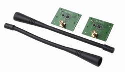
1. Kit Contents
2 x CC1101 Evaluation Modules (433 or 868-915)
2 x Antennas (type depending on frequency)
Documentation
The RF boards in this kit are designed to comply
with ETSI, FCC and IC regulations over
temperatures from 0 to +35°C.
Antenna types:
868-915 MHz: Pulse W5017, 2 dBi
420-470 MHz: Pulse SPWH24433TI, 0 dBi
(picture may deviate)
2. How to use the modules
The CC1101EM boards can be plugged into
several development boards from Texas
Instruments. One option is to use the
SmartRF04EB, which is included in the
CC1101DK.
Alternatively, you can use the SmartRF
Transceiver EB (sold separately as
SmartRFTrxEBK). Both boards let you run a
packet error rate (PER) test, control the device
from SmartRF™ Studio, and they can be used as
software development platforms.
For prototyping with other microcontrollers, plug
the EM into the “SoC Battery Board”
(www.ti.com/tool/soc-bb).
This guide will show how to use the modules
together with SmartRF04EB. The procedure is
similar for the SmartRF TrxEB.
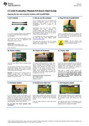
3. Plug EM into SmartRF04EB
Insert a CC1101EM (EM) with an antenna into
the SmartRF04EB (EB). The connectors will only
fit in one position, so that the EM cannot be
inserted the wrong way.
Caution! The kit contains ESD
sensitive components. Handle with care
to prevent permanent damage.
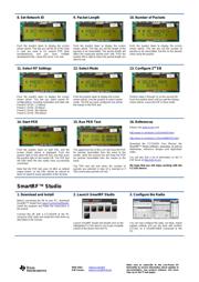
4a. Power: Battery
There are three different ways of applying power
to the EB:
The first method involves using an alkaline non-
rechargeable battery, either a 9V or a 4xAA
battery pack connected to the battery connector
on the bottom side of the board
Warning! To minimize risk of personal injury or
property damage, ONLY use alkaline non-
rechargeable batteries. Never use rechargeable
batteries to power the board.
4b. Power: DC/External
The second method applies DC power using
the DC input jack (right in picture, centre is +,
sleeve is ground), or by connecting a 4-10V
voltage source between the 4-10V and 0V
terminals of the power connector (left in
picture). It is also possible to connect a 3.3V
voltage source between the 3.3V and 0V
terminals. The on-board voltage regulators will
be bypassed in this case.
External Power Supply
1
Requirements:
Nom Voltage: 6 VDC
Max Current: 800 mA
Efficiency Level V
4c. Power: USB
The EB can also be powered from the USB bus.
Make sure that the SmartRF™ Studio software is
installed before connecting the EB to the PC;
otherwise you may experience problems in
installing it later due to driver issues.
Note that if multiple power sources are
connected, the source with the highest voltage
will power the EB. This means that you should
disconnect any attached battery when using a
lab supply or USB power; otherwise the
battery will be drained.
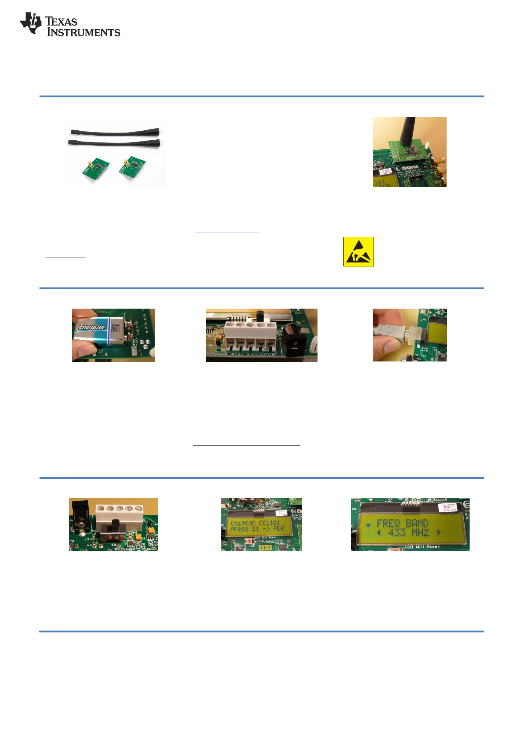
5. Set Power Switch
If a 3.3V source is used as described in 4b
above, the switch should be set to the leftmost
position. For all other cases, the switch should
be set to the rightmost position. This switch can
be used to turn off the EB by switching it to the
opposite position of that used to turn it on
Do not leave the board powered when
unattended.
6. Packet Error Rate Test
When power is applied to the board, the PER test
program will start. You should see the text shown
above on the LCD display on both evaluation
boards.
Press the button marked S1 (lower right corner)
to continue.
7. Set Frequency Band
Select the desired frequency band of operation by
using the joystick. The frequency should match
the evaluation module and antenna you are
using.
Note that the value shown in the display is also
the selected value. There is no need to press a
button to select or activate the selection.
1
When using an external power supply, make sure it meets the listed requirements in addition to complying with applicable regional product regulatory and
safety certification requirements such as UL, CSA, VDE, CCC, and PSE
器件 Datasheet 文档搜索
AiEMA 数据库涵盖高达 72,405,303 个元件的数据手册,每天更新 5,000 多个 PDF 文件
